
Buffers & Triggers
Buffer & Triggers
What Is a Trigger?
When you are debugging firmware, the waveform display shows everything your device is doing. Hundreds or thousands of events per second. Most of the time, you do not care about everything. You care about one specific moment: the exact instant your device sends a particular message, a voltage crosses a threshold, or a digital line changes state.
A trigger is a rule that tells the Active-Pro Debugger which specific event to look for. When the trigger fires (that is, when the captured data matches your rule), the software automatically snaps the waveform view to that moment in time so you can see exactly what happened just before and just after it.
Without a trigger you would have to manually scroll through potentially hours of data looking for the event you care about. With a trigger, the software does that work for you and takes you directly there.
The Buffer & Trigger tab is also where you configure how big the capture buffer is, how much pre-trigger history is kept, and when the capture should automatically stop. All of these settings work together to give you exactly the slice of captured data you want around your event.
Opening the Buffer & Trigger Tab
The Buffer & Trigger panel lives in the right-side tab bar (its icon is the magnifying glass). Click it to open the panel; the X button at the upper-left of the panel dismisses it back to the tab bar.
The panel is divided into five sections, top to bottom:
- MODE - whether the trigger system is active, and what happens when it fires.
- BUFFER - the maximum size of the capture buffer.
- TRIGGER SOURCE - what the trigger looks at and what counts as a match.
- PRE-TRIGGER - how much history before the trigger to keep.
- POST-TRIGGER - when the capture should stop after the trigger fires.
All settings take effect immediately, including mid-capture. Toggling a radio button or editing a spin box updates the active capture without needing to restart it. The one nuance: once a trigger has fired in the current capture, the pre-trigger window is locked in. Toggling between Keep everything and Keep last after that point still updates the UI and is honored on the next capture, but the pre-trigger context already captured for the current capture stays as it was.
Mode
The MODE section is the first thing you set. It controls whether the trigger system is active and what it does when a trigger fires. There are three buttons, Off, Normal, and Auto - laid out across two rows. Only one is selected at a time, and the currently selected mode is highlighted. A short, italicized description under the buttons tells you what the selected mode does.
Off
Capture runs continuously. Stops when the buffer fills. No trigger.
The trigger system is completely disabled. The TRIGGER SOURCE, PRE-TRIGGER, and POST-TRIGGER sections all dim to indicate that they are inactive. The waveform scrolls freely during a live capture and no trigger markers are placed. This is the default state when you launch the application.
Use Off when you are exploring data freely and do not need to hunt for a specific event.
Normal
Arms once. Stops after the trigger fires and post-trigger condition is met.
Each time the trigger condition is matched, the waveform snaps to that event and the TRIGGERED badge flashes on the timeline ruler. The trigger auto-rearms, so subsequent matches re-snap the view to each new trigger, but the view does not return to the live edge between triggers (that is the difference from Auto mode). The capture continues until the POST-TRIGGER stop condition you have configured is satisfied, at which point the capture halts.
Use Normal when you want the view to stay parked on the most recent trigger so you can study it, with a controlled pre- and post-trigger window around the event.
Auto
Re-arms continuously after each trigger fires.
The trigger re-arms after every event, so as triggers keep firing the waveform view keeps snapping to each new one. If triggers stop firing for one second, the view automatically reverts to live-edge scrolling, just as if you had clicked the LIVE button.
Auto mode is useful when your firmware triggers intermittently. You see each trigger when it fires, but you never end up staring at a frozen screen between events.
Buffer
The BUFFER section controls how large the capture buffer is allowed to grow.
Buffer Size
The Buffer Size: drop-down sets the cap on how much captured data is kept in memory:
| Size | Approximate samples | |
|---|---|---|
| 1 MB | 1 million | |
| 2 MB | 2 million | |
| 5 MB | 5 million | |
| 10 MB, 20 MB, 50 MB | 10-50 million | |
| 100 MB, 200 MB, 500 MB | 100-500 million | |
| 1 GB, 2 GB, 5 GB, 10 GB | 1-10 billion | |
| 100 GB | 100 billion | |
| 1 TB | 1 trillion |
When the buffer reaches this size, the capture stops automatically (the Fill buffer, then stop post-trigger option also keys off this limit). Pick the smallest size that comfortably contains the time window you need to see, a smaller buffer is faster to scroll, faster to save, and faster to load. The drop-down is purely a user cap; sustaining very large buffers in practice requires enough host RAM to hold the captured data.
Trigger Source
The TRIGGER SOURCE section defines what the trigger looks at. It has up to six controls, only some of which are visible at any one time depending on the source and condition you choose.
Source
The Source: drop-down selects the broad category of signal to monitor:
| Source | What It Monitors | |
|---|---|---|
| None (disabled) | No source selected. The trigger never fires even if MODE is set to Normal or Auto. | |
| Analog Channel | One of the analog voltage input channels (CH1-CH6). | |
| Digital Logic Channel | One of the digital logic input channels (D0-D7). | |
| Device A/B/C/D Text/Bus | Text or bus annotations on a particular debug device, the strings your firmware sends via ACTIVEText/ACTIVEprintf, or the text annotations produced by a hardware protocol decoder (UART, SPI, I²C, ...) or a Custom Decoder. |
|
| Device A/B/C/D Values | Numeric values on a particular debug device, what your firmware sends via ACTIVEValue, graphed as a numeric waveform. |
|
| Device A/B/C/D PP Graph | Numeric values produced by the Packet Presenter's graphing channels for a particular device (configured in the PacketPresenter script). |
Devices B, C, and D entries only appear in the list if your hardware supports more than one device port. On a single-device pod (Active Debugger) only Device A is offered.
Channel
The Channel: drop-down lists the available channels for the selected Source. The contents update automatically each time you change Source:
- Analog Channel - populates with
CH1...CH6. If you have given a channel a custom name on the Inputs tab, it is shown in parentheses (e.g.CH2 (VBAT)). - Digital Logic Channel - populates with
D0...D7, with custom names in parentheses where set. - Device X Text/Bus - populates only with the channels on that device that have actually produced text/bus data. Custom Decoder annotation rows appear here. Channel names from your PacketPresenter / firmware names are used where set, otherwise
Channel N. - Device X Values - populates only with channels on that device that have produced numeric values. (For Custom Decoder devices, the text channels are also surfaced here so you can trigger on
Sample.Data.) - Device X PP Graph - populates with the graphing-channel field names defined by the Packet Presenter script for that device.
Tip: Only channels that have actually received data appear here. If a channel you want is missing, enable it on the Inputs tab and let some data flow through before opening this list.
Condition
The Condition: drop-down specifies exactly what has to happen on the selected channel to fire the trigger. The available choices, and any additional controls that appear underneath, depend on the Source you chose.
Analog Channel
| Condition | When It Fires | |
|---|---|---|
| Rising Edge | The analog signal crosses the Threshold upward | |
| Falling Edge | The analog signal crosses the Threshold downward |
A Threshold: spin box appears, showing the value in volts to three decimal places, step size 0.01 V, range -100 V to +100 V.
Digital Logic Channel
| Condition | When It Fires | |
|---|---|---|
| Rising Edge | The signal transitions from low to high | |
| Falling Edge | The signal transitions from high to low | |
| Pulse High > | A high pulse lasts longer than the configured Width | |
| Pulse High < | A high pulse lasts shorter than the configured Width | |
| Pulse Low > | A low pulse lasts longer than the configured Width | |
| Pulse Low < | A low pulse lasts shorter than the configured Width |
For the four pulse-width conditions, a Width: spin box and a unit drop-down (ns / us / ms / s) appear. The numeric range in the chosen unit is 0 to 100,000.
For example, if your firmware should always produce 100 µs enable pulses but you suspect it occasionally generates spuriously short ones, set the Condition to Pulse High < with a Width of 100 µs. The trigger fires only on the short ones.
Device X Text/Bus
| Condition | When It Fires | |
|---|---|---|
| Contains | The message contains the pattern as a substring (case-insensitive) | |
| Equals | The message exactly matches the pattern, spaces included (case-insensitive) | |
| Does Not Contain | The message does not contain the pattern as a substring (case-insensitive) | |
| Does Not Equal | The message is not exactly equal to the pattern (case-insensitive) |
A Text: line edit appears, with a match text... placeholder when empty. Type the string you want to match. Text comparisons throughout the trigger system are case-insensitive.
Device X Values
| Condition | When It Fires | |
|---|---|---|
| Rising Edge | The value increases across the integer Threshold | |
| Falling Edge | The value decreases across the integer Threshold | |
| Equals | The value becomes exactly equal to the Threshold | |
| Does Not Equal | The value becomes anything other than the Threshold |
The Threshold: spin box is integer-valued for value sources (no decimal places, no V suffix), range -2,147,483,648 to +2,147,483,647.
Device X PP Graph
Same condition set as Device X Values: Rising Edge / Falling Edge / Equals / Does Not Equal, with an integer Threshold: spin box.
Pre-Trigger
The PRE-TRIGGER section controls how much capture data is preserved before the trigger event. It has two radio-button choices.
Keep everything
Default. The capture buffer stores every sample from the moment CAPTURE is pressed until the trigger fires (and after, as configured by the POST-TRIGGER section). This is the right choice when the buffer is comfortably larger than the run length, and you want unrestricted access to anything that happened before the trigger.
Keep last N seconds
Selects ring-buffer (eviction) mode. While the capture is running but no trigger has fired yet, only the most recent N seconds of data are kept; older samples are evicted. When the trigger fires, that rolling window is locked in as the pre-trigger context and stops being evicted.
A seconds spin box (range 1-60 s, default 3 s) sets the size of the rolling window. The spin box is enabled only when Keep last is selected.
Use this when you want to run the capture for a long time waiting for a rare event, without exhausting the buffer on pre-trigger data you do not care about.
Note: Toggling between Keep everything and Keep last, or changing the seconds value, takes effect immediately during a live capture as long as no trigger has fired yet. Once a trigger fires the pre-trigger window is locked in for the current capture, and further toggles affect only the next capture.
Post-Trigger
The POST-TRIGGER section controls when the capture should stop after the trigger fires. It has three mutually-exclusive radio-button choices.
Fill buffer, then stop
Default. After the trigger fires, the capture keeps running normally until the Buffer Size limit (set in the BUFFER section) is reached, at which point the capture stops automatically.
Stop after N seconds
When the trigger fires, a one-shot timer starts. After N seconds elapse, the capture stops automatically.
A seconds spin box (range 1-86,400 s, default 5 s) sets the delay. The spin box is enabled only when this radio is selected.
While the timer is running, the trigger status badge on the timeline ruler shows Stopping in Ns (counting down each second) so you can see exactly how long until the capture ends.
Stop after N triggers
The capture keeps running and counts how many times the trigger has fired. When the count reaches N, the capture stops.
A triggers spin box (range 1-1,000,000, default 1) sets the trigger count. The spin box is enabled only when this radio is selected.
While the count is below the limit, the timeline ruler badge shows Stopping in N (where N is the remaining count). When the limit is reached, the badge briefly shows Stopping... until the capture actually halts.
Tip: "Stop after 1 trigger" combined with Normal MODE is the classic single-shot capture: arm once, see exactly one event, stop. Combine larger trigger counts with Auto MODE for systematic batch capture of N consecutive events.
How Triggers Appear in the Waveform
When the trigger system is active, four visual elements appear in the waveform display:
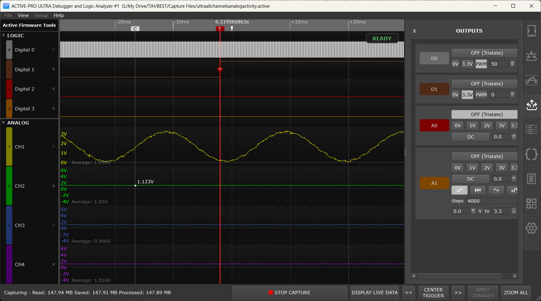
Trigger Status Badge
A small rounded badge floats over the timeline ruler at the top of the waveform display and tells you the live status of the trigger system. Its background and border colors follow the dark/light theme; only the text and color change with state:
| Badge | Color | Meaning | ||
|---|---|---|---|---|
| READY | green | Capture is running and the trigger is armed, waiting for a match | ||
| TRIGGERED | red | A trigger just fired, the badge flashes briefly | ||
| Stopping in Ns | cyan | POST-TRIGGER Stop after N seconds countdown is running | ||
| Stopping in N | cyan | POST-TRIGGER Stop after N triggers count remaining | ||
| Stopping... | cyan | Stop-after-triggers limit reached; capture is about to halt |
The badge is only shown during a live capture when MODE is not Off.
Trigger Cursor
A solid red vertical line is drawn through the entire waveform area at the timestamp of the currently focused trigger. This is the "you are here" marker; it stays visible at all zoom levels and as you pan, and is distinct from the dashed X1/X2 measurement cursors.
Trigger Diamonds
A small red diamond with a white T is drawn at the precise sample that caused each trigger to fire (on the edge, pulse, or text event that matched your condition). When you zoom out far enough that multiple triggers fall in the same pixel column, only one diamond is drawn per pixel so the display does not become a solid red bar.
Snap-to-Trigger
In Normal and Auto modes, when the trigger fires, the waveform automatically snaps so that the trigger falls at a fixed horizontal position in the window. You always see the same amount of pre-trigger data on the left and post-trigger data on the right, regardless of where in the capture the trigger occurred.
Navigating Between Triggers
Three buttons in the main status bar at the bottom of the window let you jump between recorded triggers:
<< (Prev / Pan Left)
Dual-purpose. If at least one recorded trigger is currently visible in the waveform window, this button jumps the view backward to the previous trigger event. If no trigger is on screen, it instead pans the waveform left by half its visible width, so you can scroll backward through long captures with the same button.
The button auto-repeats if you hold it down.
Tool tip: Prev trigger if one is on screen; otherwise pan left half-screen.
CENTER TRIGGER
Centers the most recent trigger event horizontally in the waveform window at the current zoom level. Use this if you have scrolled or zoomed away and want to return to the trigger position.
The button is disabled when no triggers have been recorded yet.
>> (Next / Pan Right)
The mirror of <<. Jumps forward to the next trigger when one is on screen, otherwise pans the waveform right by half its visible width. Same auto-repeat behavior as <<.
Tool tip: Next trigger if one is on screen; otherwise pan right half-screen.
Adjusting the View Around a Trigger
Once the waveform has snapped to a trigger, you can use the normal waveform navigation controls to look around without losing your place:
- Mouse scroll wheel - zoom in or out, keeping the trigger visible at a different scale
- Left-click and drag - pan the waveform left or right
- I / O keys - zoom in or out at the current mouse position
- Arrow Left / Arrow Right - on a focused text/bus/packet row, jump to the previous/next decoded event; on other rows, nudge the view by a small step
Clicking CENTER TRIGGER at any time snaps back to the trigger at the current zoom level.
Automation API
For scripted workflows, the Automation API exposes the same navigation as NextTrigger, PrevTrigger, FirstTrigger, LastTrigger, GoToTrigger <n>, CenterTrigger, and GetTriggerCount. See Automation API.
Re-running Triggers Against Captured Data
Trigger detection runs in two places:
- During a live capture, the trigger system continuously evaluates incoming samples against your settings as they arrive.
- Against the existing buffer when you click the APPLY CHANGES button in the bottom status bar.
The APPLY CHANGES button is the right thing to press any time you have changed the trigger settings (or a custom decoder, or a packet presenter script) and want the change to take effect against data you have already captured. It reprocesses the entire capture in this order: Custom Decoders, then Packet Presenters, then a Trigger Search across all channel data. The button is enabled when reprocessing is needed and disabled while a live capture is running.
Note: APPLY CHANGES can take noticeable time on very large captures. The trigger diamonds and the cursor snap update when it completes.
Practical Examples
Catching a firmware crash
Your device resets unexpectedly. Capture the 5 seconds of activity that led up to the reset:
- MODE: Normal
- Source: Digital Logic Channel
- Channel: the reset line
- Condition: Falling Edge (reset is usually active-low)
- PRE-TRIGGER: Keep last 5 seconds
- POST-TRIGGER: Stop after 1 second
When the device resets, the trigger fires, the previous 5 seconds of activity are preserved as pre-trigger context, and one second of post-reset activity is captured before the capture halts.
Detecting a glitch
You suspect your power rail occasionally drops below 2.5 V:
- MODE: Normal
- Source: Analog Channel
- Channel: your power rail (e.g. CH1)
- Condition: Falling Edge
- Threshold: 2.500 V
Any time the rail dips below 2.5 V, the trigger fires and the waveform shows you the transient.
Finding a specific log message
Your firmware logs many messages but you only care about "FAULT":
- MODE: Auto (watch every occurrence live), or Normal + POST-TRIGGER Stop after 1 trigger to grab just the first one
- Source: Device A Text/Bus
- Channel: the ADP channel your firmware uses
- Condition: Contains
- Text:
FAULT
Click APPLY CHANGES afterward to scan data you have already captured for the same pattern.
Isolating a short glitch pulse
A chip enable line should always be asserted for at least 500 µs, but you suspect occasional glitches:
- MODE: Normal
- Source: Digital Logic Channel
- Channel: the enable line
- Condition: Pulse High <
- Width: 500 µs
Only pulses shorter than 500 µs cause the trigger to fire.
Batching a fixed number of events
Capture exactly 100 consecutive UART receive packets into one file:
- MODE: Normal
- Source: Device A Text/Bus
- Channel: the UART RX channel
- Condition: Contains
- Text: (leave empty, matches every packet)
- PRE-TRIGGER: Keep everything
- POST-TRIGGER: Stop after 100 triggers
Press CAPTURE and walk away, the capture stops automatically after the 100th packet.
Triggering on a Packet Presenter graphed value
Your I²C protocol decoder feeds the Packet Presenter, which extracts a Temperature field and graphs it. Trigger when that parsed value crosses 80:
- MODE: Normal
- Source: Device A PP Graph
- Channel: Temperature
- Condition: Rising Edge
- Threshold: 80
The trigger fires the first time the parsed temperature crosses 80, regardless of the raw I²C bytes that produced it.
Triggering on Custom Decoder output
A Python Custom Decoder attached to Device B emits a Decode Error annotation row whenever it sees a malformed frame. Trigger on it:
- MODE: Auto
- Source: Device B Text/Bus
- Channel: the decoder's
Decode Errorrow - Condition: Contains
- Text:
Decode Error
Each decode error becomes a recorded trigger you can step through with << / >> afterward.
Related Pages
- Capture: starting, stopping, and saving captures
- Waveform View: zooming, panning, cursors, and measurements
- Channels and Signals: enabling input channels for capture
- Custom Decoders: Python decoders whose annotations can drive triggers
- Active Debug Port: Firmware Integration: sending text and values from firmware with
ACTIVEText,ACTIVEprintf, andACTIVEValue - Automation API: scripted control of the trigger system