
Capture
Capture
How Capture Works
When you start a capture, the application opens a continuous USB data stream from the hardware, decodes the protocol data in real time, and feeds the waveform display.
Captures can be dramatically larger than physical memory, you can capture for hours and the application keeps pace as long as the configured Buffer Size is not exceeded. When the configured Buffer Size is reached, the behaviour depends on the Buffer & Trigger settings:
- With MODE = Off, the capture stops automatically when the buffer fills.
- With MODE = Normal or Auto, the post-trigger condition (fill buffer, stop after N seconds, or stop after N triggers) determines when the capture halts.
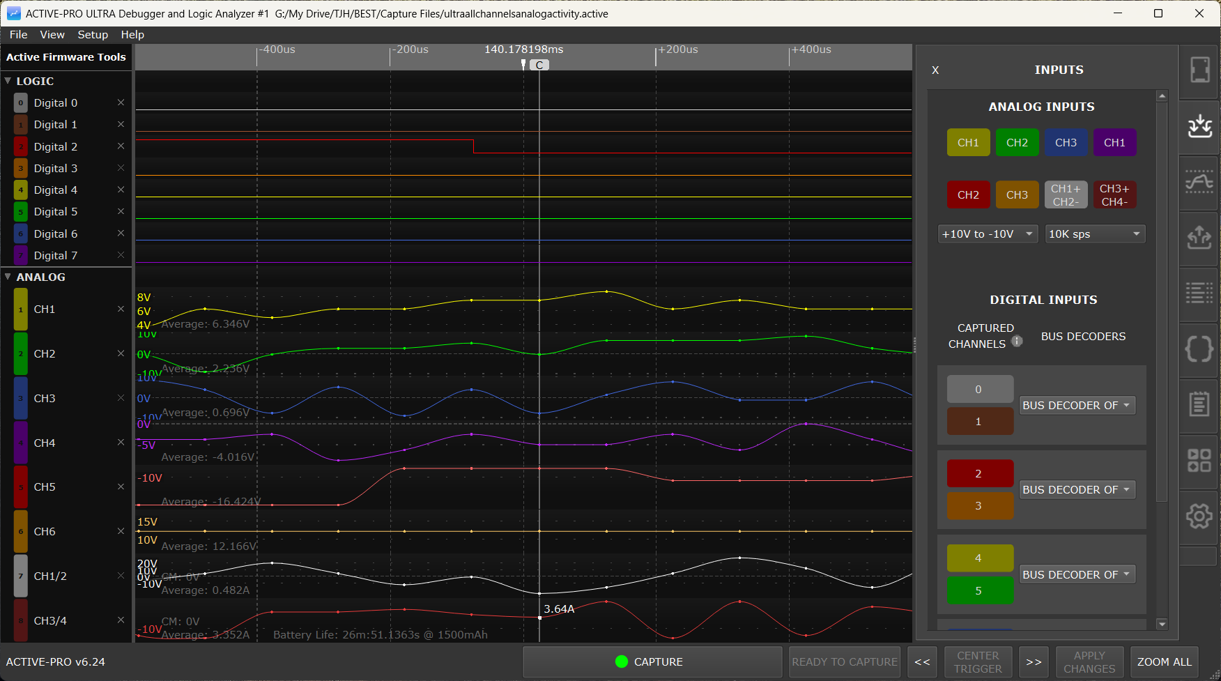
The Active-Pro™ Software runs and displays the captured data from your embedded system. The software comes up ready to capture and visualize your data.
Quick Setup Configuration
The Active-Pro can capture all of the input channels simultaneously. With an Active-Pro plugged in, it can capture 8 channels of digital and 3 channels of analog at the same time (8 channels of digital and up to 8 analog on the Ultra).
Although you can individually show each signal, there are a number of Quick Configurations that let you instantly select just the channels you need. Click Setup on the menu and select the Quick Setup configuration of your choice.
Selecting Channels to Capture
Select the top tab on the right-hand side of the screen to show the Input Channel Setup window.
Analog Input Channels
To enable or disable capturing of an analog channel, click the CH1, CH2, CH3, CH4, CH5, CH6 button (CH4-CH6 Active-Pro Ultra only) or the CH12 / CH34 differential-pair buttons. Select the analog input range using the drop-down to choose 0V to +20V or +10V to -10V.
The analog sample-rate drop-down lists all 11 entries on every model: 50M sps, 20M sps, 10M sps, 5M sps, 2M sps, 1M sps, 100K sps, 10K sps, 1K sps, 100 sps, 10 sps. The effective hardware maximum depends on the connected model:
- Active-Pro: 1 Msps maximum. The higher entries in the dropdown are present but the hardware cannot honor them.
- Active-Pro Ultra: up to 50 Msps, with auto-degrade by channel count: 50 Msps requires at most 1 analog channel enabled, 20 Msps requires at most 2, and 10 Msps requires at most 4. At 5 Msps and below there is no channel-count restriction. If you enable more channels than the current rate allows, the application automatically steps the rate down to the next supported value.
- Active Debugger: no analog channels at all.
The analog channel enable buttons and the differential-pair toggle buttons (CH3+/4- on Active-Pro; CH1+/2- and CH3+/4- on Active-Pro Ultra) are on the Inputs tab. The per-channel offset, scale, and units fields, the Current Measuring Resistor (Ohms) field, and the Battery Capacity field are in the Settings tab's Analog Channel Settings section. See Channels and Signals for the full reference.
Digital Input Channels
To enable or disable capturing of a digital channel, click the 0, 1, 2, 3, 4, 5, 6, or 7 button. These buttons determine if that channel will be captured and a waveform of the signal will be displayed.
Custom Decoder auto-enable: When you attach a Custom Decoder to a port, any digital or analog channels the script declares via its
digital_channeloranalog_channelPARAM lines are forced ON for capture, even if you had previously disabled them on the Inputs tab. The application also warns you if a Custom Decoder's channels collide with channels claimed by another port. See Custom Decoders.
ACTIVE Digital Logic Threshold
The Active-Pro features variable Digital Logic Thresholds that can range from 0V to +4V. Set the logic threshold to the logic family you are using. This will set the voltage level that indicates the change from a logic "0" to a logic "1".
If this level is set incorrectly, or too close to either the top or bottom of your logic range, you will see inconsistent waveforms and this level will need to be adjusted. Five preset buttons (1.0V, 1.8V, 2.5V, 3.3V, 5.0V) on the Inputs tab snap to the recommended threshold for each common logic family.
Hardware Bus Decoders
There can be up to 4 hardware bus decoders that operate on the associated signals. These bus decoders are active even if the digital input signal is not captured. Select the type of bus by clicking the drop-down list.
Available Device Capture Types for each device A, B, C and D are grouped into three sections:
- Real-Time Hardware Decode - ACTIVE Debug Bus (2-Wire / 1-Wire / SWV), EE101 Debug Bus, I2C, UART (all variants), SPI (all variants)
- Real-Time Software Decode - 1-Wire (Dallas/Maxim), LIN, RS232, MDIO, CHSI, DS101, 9-bit UART (normal and inverted)
- Post-Capture Python Decode - CHOOSE CUSTOM DECODER… (opens the Decoder Picker)
Helpful Hint: To maximize the performance of the capture, make sure that any channels that are not necessary for a trace are turned off.
UART modes, ACTIVE 1-Wire and EE101 1-wire buses have an Auto Baud feature. When you press the Auto-Baud button, the Active-Pro measures the digital inputs for 1 second and computes the baud rate of the signals for that device at that time. It then sets the baud rate setting to the value calculated.
Starting a Capture
Press Space or click the CAPTURE button in the status bar.
The button label immediately changes to STOP CAPTURE. The waveform display begins updating in real time as data arrives and is decoded. The total number of captured bytes is displayed at the bottom during capture.
If a trigger is configured (MODE = Normal or Auto in the Buffer & Triggers tab), the trigger status badge appears over the timeline ruler showing READY, and snaps to TRIGGERED when the configured condition matches.
Only signals and channels that are active are shown on the display automatically, if your firmware only outputs data on one channel, only that channel appears.
During a live capture, you can scroll backward in the waveform to review earlier data. The DISPLAY LIVE DATA button in the status bar becomes active; click it to jump back to the end and resume auto-scroll.
Stopping a Capture
Press Space or click STOP CAPTURE in the status bar.
The capture ends and the waveform is now fully navigable. All data from the beginning to the end of the capture is available.
After the USB stream has fully drained, the application runs the post-capture pipeline in this order:
- Custom Decoders - every attached Custom Decoder runs in slot order A → B → C → D. The status bar shows progress like Processing Custom Decoder: My SPI — 37% — 1450 records. Press CANCEL to skip the remaining decoders.
- Packet Presenters - re-run against whatever decoded data exists.
- Trigger Search - re-scan for trigger matches across the now-current channel data.
Pressing Capture again will erase the previous capture and start a new one.
The capture can also stop automatically based on the POST-TRIGGER condition you configured in the Buffer & Triggers tab, Fill buffer, then stop, Stop after N seconds, or Stop after N triggers.
Starting a New Capture
File > New Capture clears all current capture data and resets the waveform display to empty.
All settings are preserved: channel names, decoder modes, colors, PacketPresenter definitions, attached Custom Decoder scripts and parameters, trigger settings, and notes all remain. Only the captured waveform data is cleared.
Capture File Settings
These settings are split between the Buffer & Triggers tab (buffer size) and the Settings tab (working directory, sample rate).
Working Directory
The folder where the capture data file is written during capture. Click the ... button in the Settings tab to browse for a different folder.
Tip: Set the working directory to a fast local drive. For very large captures (hundreds of GB), use an SSD.
Each running instance of the application stores its capture data in a per-pod subdirectory of the working directory, so multiple instances do not collide. The same working directory also hosts the shared decoder folder (<working directory>/decoders by default) where Custom Decoder .py files live.
Buffer Size
In the Buffer & Triggers tab's BUFFER section, the Buffer Size: drop-down sets the cap on how much captured data is kept in memory before the capture stops or wraps. Entries (top to bottom in the drop-down):
1 TB · 100 GB · 10 GB · 5 GB · 2 GB · 1 GB · 500 MB · 200 MB · 100 MB · 50 MB · 20 MB · 10 MB · 5 MB · 2 MB · 1 MB
Pick the smallest size that comfortably contains the time window you need to see, a smaller buffer is faster to scroll, faster to save, and faster to load. See Buffer & Triggers for how Buffer Size interacts with pre- and post-trigger settings.
Analog Sample Rate
The analog sample-rate drop-down (SampleRateAnalog on the Inputs tab) sets the analog channel sample rate. The digital channel sample rate is fixed at the hardware maximum for each model.
The drop-down shows all 11 entries on every model (top to bottom):
50M sps · 20M sps · 10M sps · 5M sps · 2M sps · 1M sps · 100K sps · 10K sps · 1K sps · 100 sps · 10 sps
The effective hardware maximum depends on the model:
- Active-Pro: 1 Msps. Higher entries in the dropdown are shown but the hardware cannot honor them.
- Active-Pro Ultra: up to 50 Msps, auto-degraded by channel count. 50 Msps requires at most 1 analog channel enabled, 20 Msps requires at most 2, and 10 Msps requires at most 4. At 5 Msps and below there is no channel-count restriction. If you enable more channels than the current rate allows, the application automatically steps the rate down to the next supported value.
- Active Debugger: no analog channels.
Reducing the analog sample rate reduces capture file growth rate, extending how long you can capture before the buffer fills.
Saving a Capture
Save Entire Capture
File > Save Capture saves the entire current capture to a .active file. A save dialog appears if this capture has not been saved before. Saving large buffer sizes can take a while; a percentage complete is displayed at the bottom of the application.
The .active file stores everything needed to restore the session exactly:
- All captured waveform data (logic, analog, Active Debug Port, PacketPresenter output, Custom Decoder annotations)
- Channel names, colors, and visibility settings
- Decoder mode for each device port
- PacketPresenter definitions
- Attached Custom Decoder scripts, parameters, and enabled flag - the full
.pytext is saved into the file so a colleague can open the capture and see the same decoded output without needing your decoder folder - Buffer & Trigger settings (mode, source, condition, thresholds, pre- and post-trigger configuration, recorded trigger positions)
- Analog calibration settings (Active-Pro and Active-Pro Ultra)
- Notes (rich text)
- Analysis Context text
Save Between Cursors
File > Save Between Cursors saves only the data within the X1-to-X2 cursor range to a new .active file. This is useful for extracting a specific event from a long capture and saving it as a smaller, focused file to share with a colleague or attach to a bug report.
Opening a Capture
File > Open Capture opens a .active file. The application restores all waveform data, settings, channel names, decoder configuration, attached Custom Decoder scripts, trigger configuration, and notes from the file. Opening files with large buffer sizes can take a while to decompress and display.
If the file contains attached Custom Decoder scripts, they re-run automatically against the loaded capture so you see the same annotation rows the original capture had. The .active file is the source of truth, even if the bundled .py files in your decoder folder have changed since the capture was saved, the version embedded in the file is what runs.
Recent Files
File > Recent Files lists the last 5 .active files you have opened or saved. Click any entry to open it immediately.
Configuration Files
Available on: Active-Pro · Active-Pro Ultra (the Save/Open Configuration menu items are hidden on Active Debugger)
A configuration file saves your settings, decoder modes, channel names, PacketPresenter definitions, trigger settings, without saving any capture data. Configuration files are useful for sharing a channel setup with a colleague or quickly reconfiguring the tool for a different project.
File > Save Configuration writes the current settings to a .active file. The configuration file is much smaller than a full capture because it contains no captured waveform data.
File > Open Configuration loads settings from a configuration file and applies them to the current session. Captured waveform data is not affected.
A configuration file includes: channel names, decoder modes, baud rate and decoder settings, analog offset/scale/units per channel, PacketPresenter definitions, Buffer & Trigger settings, and channel visibility settings. Custom Decoder script bodies are not stored in configuration files, only the script filename. To ship a complete project to a colleague, save the configuration file plus the underlying decoder .py files (or share a .active capture, which embeds the script bodies).