
Channels and Signals
Channels and Signals
The Active-Pro software can display several different types of signal data simultaneously on a shared time axis. Which types are available depends on your hardware model.
Channel Types by Model
| Channel Type | Active Debugger | Active-Pro | Active-Pro Ultra | |||
|---|---|---|---|---|---|---|
| Logic channels (D0-D7) | no | yes | yes | |||
| Analog channels | no | 3 channels (CH1-CH3) + CH3+/4- diff | 6 single-ended (CH1-CH6) + 2 diff pairs | |||
| Active Debug Port, port A | yes | yes | yes | |||
| Active Debug Port, ports B, C, D | no | yes | yes | |||
| PacketPresenter channels | port A only | ports A-D | ports A-D | |||
Graphing channels (PP fields with .G) |
yes | yes | yes | |||
| Custom Decoder annotation rows | port A only | ports A-D | ports A-D |
Logic Channels (D0-D7)
Available on: Active-Pro · Active-Pro Ultra
Eight digital logic analyzer inputs. Each shows a binary waveform (high or low) on the timeline. The Active-Pro samples at up to 120 Msps for waveform display (240 Msps for hardware decoder framing); the Ultra samples at up to 500 Msps.
Enabling Logic Channels
Open the Inputs tab on the right-side panel. Eight buttons labeled D0 through D7 toggle each logic channel on and off. Channels that are disabled are not captured and do not appear in the waveform area, this is a good way to reduce data volume when you only need some inputs.
Tip to maximize capture performance: Turn off any channels that are not necessary for a trace.
Custom Decoder auto-enable: When you attach a Python Custom Decoder to a port, any channels that the decoder declares via a
digital_channelPARAM are forced ON for capture, even if you had previously disabled them on the Inputs tab. The firstdigital_channelparameter on each port defaults to that port's home pair: A → channels 0/1, B → 2/3, C → 4/5, D → 6/7.
Logic Input Threshold
The digital input threshold voltage determines at what point a signal is read as logic high versus logic low. The Active-Pro features a variable Digital Logic Threshold that can range from 0 V to +4 V. Set this to the logic family you are using, roughly halfway between the low and high voltage levels of your target. The default is appropriate for 3.3 V logic.
Five preset buttons on the Inputs tab snap to the recommended threshold for each common logic family:
| Button | Threshold | For logic family | ||
|---|---|---|---|---|
| 1.0V | ≈ 0.5 V | 1.0 V | ||
| 1.8V | ≈ 0.9 V | 1.8 V | ||
| 2.5V | ≈ 1.25 V | 2.5 V | ||
| 3.3V | ≈ 1.65 V | 3.3 V (default) | ||
| 5.0V | ≈ 2.5 V | 5.0 V |
The threshold affects all logic channels simultaneously. If the level is set incorrectly or too close to either the top or bottom of your logic range, you will see inconsistent waveforms.
Analog Channels
Available on: Active-Pro · Active-Pro Ultra
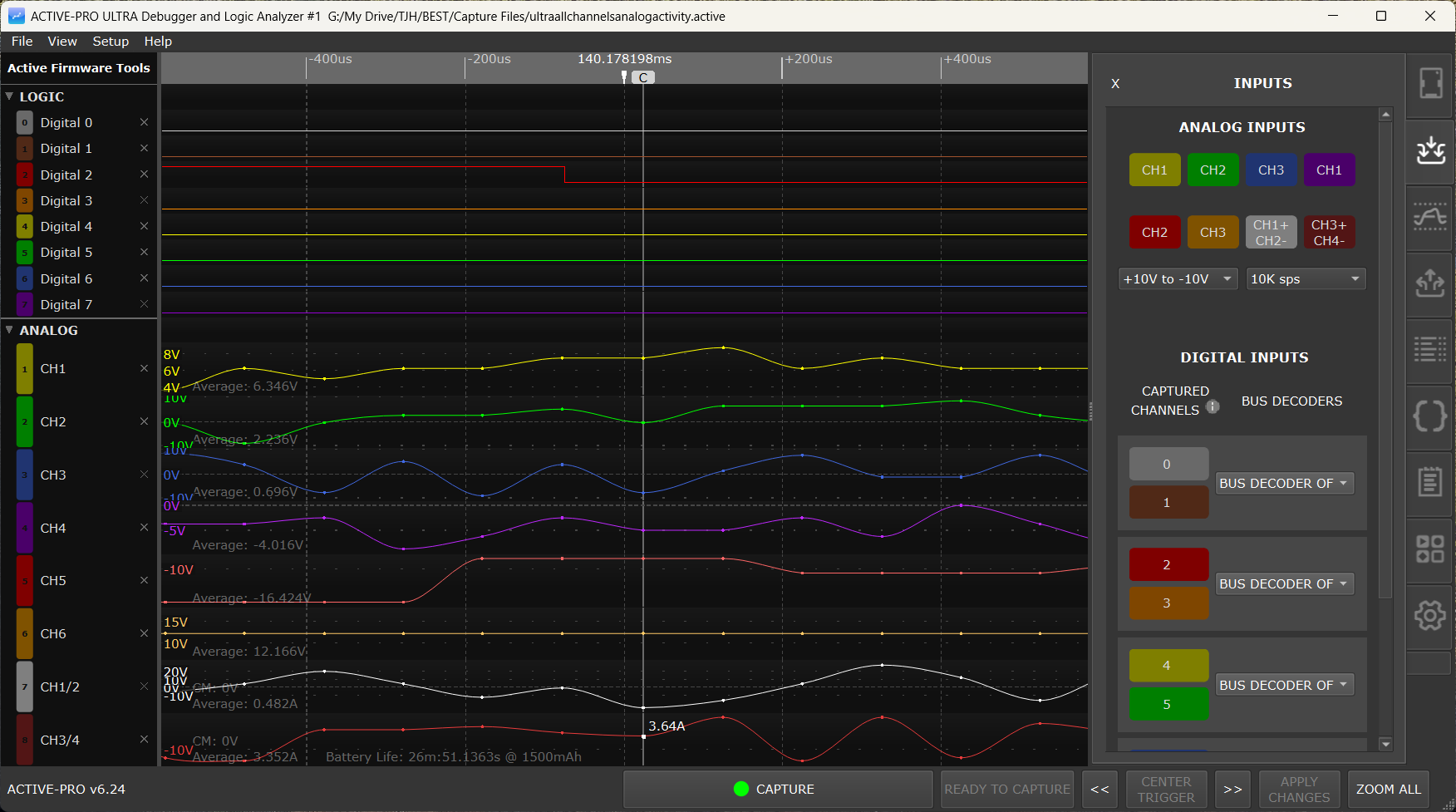
Active-Pro has 3 analog channels (CH1-CH3) plus a CH3+/4- differential pair. Active-Pro Ultra has 8 analog channels: 6 single-ended (CH1-CH6) plus 2 differential pairs (CH1+/2- and CH3+/4-).
Each analog channel displays a continuous voltage waveform on the timeline. The current voltage at the Current Cursor position is shown in the channel's name column and updates live as the cursor moves.
Enabling Analog Channels
Analog channels are enabled alongside the logic channels in the Inputs tab. Select the analog input range using the drop-down to choose 0V to +20V or +10V to -10V. Select the analog sample rate using the drop-down: 11 entries from 10 sps to 50M sps. The effective hardware maximum is 1 Msps on Active-Pro and up to 50 Msps on Active-Pro Ultra (auto-degraded by enabled-channel count).
Analog Channel Settings (in the Settings Tab)
Per-channel configuration (Offset, Scale, Units), the Current Measuring Resistor, and the Battery Capacity live in the Settings tab's Analog Channel Settings section, not the Inputs tab. There is no separate pop-up dialog. Edits take effect as you type.
Differential Mode Buttons
The differential-pair toggle buttons are on the Inputs tab, next to the analog channel enable buttons. On Active-Pro the available pair button is CH3+/4-; Active-Pro Ultra adds a second pair button, CH1+/2-. The buttons are toggles, click again to return to single-ended mode. Once a pair is in differential mode, that pair's Offset, Scale, and Units fields become available in the Settings tab's Analog Channel Settings section.
Active-Pro Ultra: Six channels (CH1-CH6) operate single-ended (-10 V to +10 V measurable, -30 V to +30 V tolerant). Two differential pairs are also available: CH1+/CH2- and CH3+/CH4-.
Use differential mode when measuring signals that are referenced to a voltage other than ground, for example, across a current sense resistor.
Per-Channel Offset, Scale, and Units
For each channel (and each active differential pair):
| Setting | Default | Description | ||
|---|---|---|---|---|
| Offset | 0.0 | Added to the raw voltage before display. Use this to shift the waveform up or down. | ||
| Scale | 1.0 | Multiplier applied after offset. Use this to convert voltage to an engineering unit. | ||
| Units | V | Label shown on the waveform y-axis and in the name column. |
Example: To display current in milliamps from a 1 Ω shunt resistor:
- Offset: 0.0
- Scale: 1000.0 (converts volts to milliamps)
- Units: mA
Current Measuring Resistor
Enter the value of your shunt resistor (in ohms) in the Current Measuring Resistor (Ohms) field in the Settings tab's Analog Channel Settings section. This value is used by the current-related calculations elsewhere in the application (battery-life estimation, current display in calibrated channels).
Use the differential pair (CH1+/CH2- or CH3+/CH4-) for current measurement to avoid ground reference errors when the shunt is not at the circuit ground potential.
Choosing a shunt resistor value: Pick a resistor that produces roughly 0.1 V drop at your expected maximum current. This maximizes measurement resolution while staying within the input range.
| Max current | Suggested resistor | |
|---|---|---|
| 10 mA | 10 Ω | |
| 50 mA | 2 Ω | |
| 100 mA | 1 Ω | |
| 500 mA | 200 mΩ | |
| 1 A | 100 mΩ |
Battery Capacity
Enter your battery capacity in the Battery Capacity (mHr) field next to the Current Measuring Resistor field. The on-screen label reads "mHr" but the value is interpreted as milliamp-hours (mAh). When current measurement is configured, the application uses the measured current waveform plus this capacity to estimate remaining battery life.
Calibration
Analog channel calibration is launched from Setup > Calibrate Analog Channels, not from the Inputs tab. Stored calibration values are viewable via Setup > Show Calibration Values.
Active Debug Ports
Port A available on: Active Debugger · Active-Pro · Active-Pro Ultra Ports B, C, D available on: Active-Pro · Active-Pro Ultra
Active Debug Ports carry live debug data streamed directly from your microprocessor or FPGA firmware. Your firmware uses the ACTIVE library to log text strings, printf-formatted messages, and numeric variable values on named channels. This data appears in real time in the waveform display and the List tab, timestamped to nanosecond resolution.
Each port supports up to 64 named channels and 64 graphable variables. Channel names are defined in your firmware using ACTIVELabel().
Active Debug Port Modes
Each device port must be configured with the matching decoder mode for how your firmware transmits data:
| Mode | Connection | Max Speed | Notes | |||
|---|---|---|---|---|---|---|
| Active Debug Port (2-Wire) | Clock + Data pins | Up to 80 Mbps | Recommended for highest throughput | |||
| Active Debug Port (1-Wire UART) | Data pin only (UART TX) | Baud-rate dependent | Uses existing UART hardware on your MCU | |||
| Active Debug Port (1-Wire SWV) | SWV/ITM output on ARM Cortex | Baud-rate dependent | No extra GPIO pins needed on Cortex-M devices |
Select the mode in the Inputs tab using the AMode (or BMode, CMode, DMode) selector.
Active Debug Port Data Types
Text events (ACTIVEText, ACTIVEprintf): Appear as labeled text items on the channel's waveform row. Visible in the waveform and listed chronologically in the List tab. Each event has a precise timestamp. Clicking an event in the waveform jumps the List tab to that event. Clicking in the List tab scrolls the waveform to that timestamp.
Numeric values (ACTIVEValue): Appear as a continuous line graph on the channel's waveform row. The value is plotted against time, giving you a visual trace of how the variable changes.
Channels Appear Automatically
You do not need to pre-configure the Active Debug Port channels in the software. As data arrives, new channels appear automatically in the waveform area with the names sent by your firmware.
Showing and Hiding Active Debug Port Channels
Individual channels within a device port can be shown or hidden by clicking the enable/disable control on the left side of each channel's name column. Hiding a channel does not stop it from being decoded, it just removes it from the waveform display and excludes it from AI Snapshot and CSV exports.
Tip for AI Snapshot and CSV export: Before exporting, hide any channels you do not want included in the output. Only visible (enabled) channels are included in AI Snapshots and CSV exports. This is very useful when you have many channels and want to focus on specific ones.
PacketPresenter Channels
When a PacketPresenter definition is active for a device port, a PP channel row appears in the waveform area below the raw decoded row for that port. This row shows the structured, named packet fields parsed from the byte stream by the PacketPresenter engine.
See PacketPresenter for full documentation.
Graphing Channels
Any numeric field in a PacketPresenter definition that uses the .G output modifier automatically generates a graphing channel row in the waveform area, below the PP row. This row displays a line chart of that field's value plotted over time, allowing you to visualize trends in bus data.
The graphing channel is named after the PP field name automatically.
Custom Decoder Annotation Rows
When a Custom Decoder (Python) is attached to a device port, the decoder emits one or more annotation rows for that port. Each append() call in the decoder script names a channel index from 0-7 within that port's slot. The annotation rows appear in the waveform display just like hardware-decoded rows, they support PacketPresenter parsing on top, AI Snapshot export, CSV export, and trigger conditions.
See Custom Decoders for the full reference.
Channel Groups and Collapsing
Channels are organized into collapsible groups in the waveform area:
- Logic channels as a group
- Analog channels as a group
- Each Active Debug Port device (A, B, C, D) as its own group
- Custom Decoder annotations appear within their device's group
Click the group header row (the darker row at the top of each group) to collapse or expand all channels in that group. Collapsing a group hides its channels from view without stopping capture or decode, it just saves screen space.
Renaming Channels
Double-click any channel name in the name column to enter edit mode. Type the new name and press Enter to confirm, or Escape to cancel.
Channel names are saved in the capture file and in configuration files. If you give meaningful names to your Active Debug Port channels in firmware using ACTIVELabel(), those names come through automatically and you may not need to rename them in the software at all. Custom channel names that you give analog or logic channels also appear in parentheses in the Buffer & Triggers tab channel dropdown (e.g. CH2 (VBAT) or D3 (CS_FLASH)).
Reordering Channels
Click and hold on the name column (the tab on the left) of any channel row. Drag it up or down to move it to a new position in the waveform display. Release to drop. The new order is saved in the capture file.