
Signal Generators
Signal Generators
Available on: Active-Pro · Active-Pro Ultra
The Active-Pro has built-in digital and analog signal generators. These are controlled from the Outputs tab on the right-side panel, and can also be fully automated via the Automation API.
Digital Signal Generators (D0 and D1)
The Active-Pro has 2 Digital Signal Generators built in. It outputs a digital voltage on the D0 and D1 signals.
Each of the digital lines can have one of the modes below by selecting the associated radio button:
| Mode | Description | |
|---|---|---|
| Tristate | Pin is not driven, high impedance. Safe default. | |
| Logic Low (0V) | Pin is driven to 0V | |
| Logic High (3.3V) | Pin is driven to 3.3V | |
| PWM | Pulse Width Modulator, square wave output at 250 kHz (Active-Pro) or 390 kHz (Active-Pro Ultra). A duty cycle control sets the on-time percentage from 0% to 100%. |
Output drive capability: 8 mA max per pin.
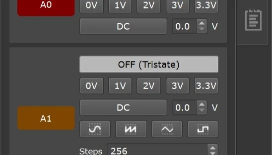
Analog Signal Generator (A0 and A1)
The Active-Pro has an Analog Signal Generator built in. It outputs a voltage pattern on the A0 and A1 signals.
A0 can be set to:
| Mode | Description | |
|---|---|---|
| Tristate | Not driven (high impedance) | |
| 0 V | Fixed DC output at 0 V | |
| 1 V | Fixed DC at 1 V | |
| 2 V | Fixed DC at 2 V | |
| 3 V | Fixed DC at 3 V | |
| 3.3 V | Fixed DC at 3.3 V | |
| DC | Custom DC voltage, set with the voltage spin box |
A1 supports all of the above A0 modes, plus waveform output modes:
| Mode | Description | |
|---|---|---|
| Sine | Sinusoidal waveform | |
| Ramp | Linear ramp waveform, sweeping from minimum to maximum voltage | |
| Square | Square wave (50% duty cycle) | |
| Triangle | Triangular waveform |
For waveform modes, set the minimum and maximum output voltage using the controls (0V to 3.3V range). Frequency is adjusted via the Steps setting, the number of steps per waveform cycle. Each step is 4 µsec.
Waveform frequency range:
- Active-Pro: 62.5 Hz to 25 kHz
- Active-Pro Ultra: 62.5 Hz to 7.25 kHz
Tips
Testing power supply response: Set A0 to a DC level matching your circuit's supply voltage, then switch it to 0 V and watch the analog input channels on the same timeline to measure your power supply's response time.
ADC transfer function: Drive A1 with a ramp waveform and connect it to your target's ADC input while monitoring the ADC readings via the Active Debug Port. This gives you a complete ADC transfer function with one capture.
Combine with triggers: Trigger on a Device Values channel to capture exactly the moment your firmware reacts to a stimulus you're driving with A1. Useful for measuring code-to-output latency.
All output settings can also be controlled via the Automation API, see Automation API for the SetD0Mode, SetD1Mode, SetA0Mode, SetA1Mode, and related commands.