
Automation API
Automation API
The Active-Pro software includes a built-in TCP socket server that lets any external program control the application using simple text commands. You can start and stop captures, read live signal values, control output pins, move cursors, configure triggers and the capture buffer, navigate between recorded triggers, export data, and more, all from a test script, CI pipeline, another application, or a command-line terminal.
This API is available in software version 3.8 and above. The trigger-related commands documented in this chapter were added in 6.x.
MCP Server: If you want AI assistants such as Claude Desktop to control the Active-Pro application directly in plain English, the MCP Server wraps this API for you. It requires no code, just install the server once and ask Claude to run captures, search data, configure triggers, or export snapshots.
Connecting
The server listens on localhost (127.0.0.1) only. External network connections are not accepted.
Default port: 37800
When multiple instances of the application are running simultaneously (one per connected device), each uses a different port:
- Instance 1: port 37800
- Instance 2: port 37801
- Instance 3: port 37802
Connect with any TCP socket client. The server accepts one connection at a time; a new connection closes the previous one.
Command format:
- Send a plain ASCII string terminated with a single newline (
\n, hex0x0A) - Do not use
\r\n- commands must end with\nonly - Commands are case-insensitive
- The server responds with an uppercase ASCII string followed by
\n - Send one command and wait for the response before sending the next
Unrecognized commands return: ERROR UNRECOGNIZEDCOMMAND
Quick Start (Python)
import socket

def cmd(sock, command):
    sock.sendall((command + '\n').encode('ascii'))
    return sock.recv(1024).decode('ascii').strip()

s = socket.socket(socket.AF_INET, socket.SOCK_STREAM)
s.connect(('127.0.0.1', 37800))

print(cmd(s, 'Hello')) # -> HELLO
print(cmd(s, 'isConnected')) # -> YES or NO
print(cmd(s, 'StartCapture')) # -> OK
# ... run your test ...
print(cmd(s, 'StopCapture')) # -> OK (blocks until decoders/PP/Trigger Search finish)
print(cmd(s, 'SaveCapture C:/captures/test1.active')) # -> OK
s.close()
Command Reference
Connection and Status
| Command | Response | Description | ||
|---|---|---|---|---|
Hello |
HELLO |
Verifies the connection is live | ||
isConnected |
YES or NO |
Is a hardware device currently connected? | ||
isCapturing |
Yes or No |
Is a capture currently in progress? | ||
GetDevicesAttached |
Name list | Return a newline-separated list of all attached hardware devices, one per line. Use the line index (1-based) with SelectDevice. Returns NONE if no devices are detected. |
||
SelectDevice <index> |
OK |
Switch to the hardware device at the given 1-based index from the GetDevicesAttached list. Clears current capture data and resets to default settings. Returns ERROR INVALIDINDEX if out of range. |
Capture Control
| Command | Response | Description | ||
|---|---|---|---|---|
StartCapture |
OK |
Start a capture | ||
StartCapture |
AlreadyStarted |
Capture is already running | ||
StartCapture |
NOACTIVEDEVICE |
No hardware device is connected | ||
StopCapture |
OK |
Stop the current capture. Waits for the post-capture pipeline (Custom Decoders, Packet Presenters, Trigger Search) to drain before returning. On very long captures with heavy decoding, a subsequent SaveCapture / ExportBetweenCursors may run against partially-processed data. |
||
StopCapture |
NotStarted |
No capture is running | ||
StopCapture |
NOACTIVEDEVICE |
No hardware device is connected | ||
NewCapture |
OK |
Clear all current capture data (equivalent to File > New Capture). Settings, attached decoders, and trigger configuration are preserved. | ||
GetCaptureSize |
Integer (bytes) | Total bytes captured and stored on disk so far | ||
GetCaptureTime |
Decimal (seconds) | Duration of the current capture in seconds |
Reading Signal Values
These commands return the current signal value at the latest captured position. Useful for polling during automated test sequences.
| Command | Response | Description | ||
|---|---|---|---|---|
GetLogic |
Integer (0-255) | Current state of the 8 digital logic inputs as a bitmask. Bit 0 = D0, bit 7 = D7. | ||
GetCH1 |
Decimal (volts) | Analog channel 1 voltage | ||
GetCH2 |
Decimal (volts) | Analog channel 2 voltage | ||
GetCH3 |
Decimal (volts) | Analog channel 3 voltage | ||
GetCH4 |
Decimal (volts) | Analog channel 4 voltage (Active-Pro Ultra only) | ||
GetCH5 |
Decimal (volts) | Analog channel 5 voltage (Active-Pro Ultra only) | ||
GetCH6 |
Decimal (volts) | Analog channel 6 voltage (Active-Pro Ultra only) | ||
GetCH4 |
NOT AVAILABLE |
Returned on non-Ultra hardware |
Digital Output Control
Available on: Active-Pro · Active-Pro Ultra
D0 Output Mode
| Command | Response | Effect | ||
|---|---|---|---|---|
SetD0Mode 0 |
OK |
D0 → Tri-state (high impedance, not driven) | ||
SetD0Mode 1 |
OK |
D0 → 0 V (logic low) | ||
SetD0Mode 2 |
OK |
D0 → 3.3 V (logic high) | ||
SetD0Mode 3 |
OK |
D0 → PWM mode | ||
SetD0PWM <0-255> |
OK |
Set D0 PWM level. 0 = 0% duty cycle, 255 = 100% duty cycle. |
D1 Output Mode
| Command | Response | Effect | ||
|---|---|---|---|---|
SetD1Mode 0 |
OK |
D1 → Tri-state | ||
SetD1Mode 1 |
OK |
D1 → 0 V | ||
SetD1Mode 2 |
OK |
D1 → 3.3 V | ||
SetD1Mode 3 |
OK |
D1 → PWM mode | ||
SetD1PWM <0-255> |
OK |
Set D1 PWM level (0-255) |
Analog Output Control
Available on: Active-Pro · Active-Pro Ultra
A0 Output Mode
| Command | Response | Effect | ||
|---|---|---|---|---|
SetA0Mode 0 |
OK |
A0 → Tri-state (not driven) | ||
SetA0Mode 1 |
OK |
A0 → 0 V DC | ||
SetA0Mode 2 |
OK |
A0 → 1 V DC | ||
SetA0Mode 3 |
OK |
A0 → 2 V DC | ||
SetA0Mode 4 |
OK |
A0 → 3 V DC | ||
SetA0Mode 5 |
OK |
A0 → 3.3 V DC | ||
SetA0Mode 6 |
OK |
A0 → Custom DC voltage (set level with SetA0DCLevel) | ||
SetA0DCLevel <voltage> |
OK |
Set A0 DC output voltage (floating-point, e.g. 1.75). Used when mode = 6. |
A1 Output Mode
| Command | Response | Effect | ||
|---|---|---|---|---|
SetA1Mode 0 |
OK |
A1 → Tri-state | ||
SetA1Mode 1 |
OK |
A1 → 0 V DC | ||
SetA1Mode 2 |
OK |
A1 → 1 V DC | ||
SetA1Mode 3 |
OK |
A1 → 2 V DC | ||
SetA1Mode 4 |
OK |
A1 → 3 V DC | ||
SetA1Mode 5 |
OK |
A1 → 3.3 V DC | ||
SetA1Mode 6 |
OK |
A1 → Custom DC voltage | ||
SetA1Mode 7 |
OK |
A1 → Ramp waveform | ||
SetA1Mode 8 |
OK |
A1 → Sine waveform | ||
SetA1Mode 9 |
OK |
A1 → Square waveform | ||
SetA1Mode 10 |
OK |
A1 → Triangle waveform | ||
SetA1DCLevel <voltage> |
OK |
Set A1 DC voltage when mode = 6 | ||
SetA1Minimum <voltage> |
OK |
Set minimum voltage for A1 waveform output | ||
SetA1Maximum <voltage> |
OK |
Set maximum voltage for A1 waveform output | ||
SetA1Steps <count> |
OK |
Set number of waveform steps (controls frequency). Each step is 4 µsec. |
Cursor Control
| Command | Response | Description | ||
|---|---|---|---|---|
SetCursorCurrent <time> |
OK |
Move the Current Cursor (C) to the given time in seconds. This is also the starting position for the Search command. |
||
SetCursorX1 <time> |
OK |
Place the X1 cursor at the given time in seconds | ||
SetCursorX2 <time> |
OK |
Place the X2 cursor at the given time in seconds | ||
GetCursorCurrent |
Time (seconds) | Return the current cursor (C) position in seconds | ||
GetCursorX1 |
Time (seconds) | Return the X1 cursor position in seconds | ||
GetCursorX2 |
Time (seconds) | Return the X2 cursor position in seconds |
Time values are floating-point seconds. Example: SetCursorX1 0.001500 sets X1 at 1.5 ms.
View and Navigation
| Command | Response | Description | ||
|---|---|---|---|---|
ZoomAll |
OK |
Fit the entire capture on screen | ||
ZoomFrom <start> <end> |
OK |
Zoom to show the time range from start to end (both in seconds). Arguments are automatically ordered, you can pass them in either order. |
||
Search <string> |
Time (seconds) | Search forward from the Current Cursor for the string. Returns the timestamp of the match as a decimal number. | ||
Search <string> |
NOTFOUND |
No match found |
The Search command is case-insensitive and searches through Active Debug Port decoded text.
Tab Visibility
| Command | Response | Description | ||
|---|---|---|---|---|
ShowInputs |
OK |
Open the Inputs tab | ||
ShowTriggers |
OK |
Open the Buffer & Triggers tab | ||
ShowOutputs |
OK |
Open the Outputs tab | ||
ShowList |
OK |
Open the List tab | ||
ShowSettings |
OK |
Open the Settings tab | ||
ShowNotes |
OK |
Open the Notes tab | ||
ShowCode |
OK |
Open the Source Code tab | ||
ShowLiveUI |
OK |
Open the Live UI tab | ||
ShowDevices |
OK |
Open the Devices tab | ||
CloseTabs |
OK |
Close the currently open tab (collapse the panel) |
Waveform Device Visibility
Show or hide an individual device's rows in the waveform view (A = device 0, B = device 1, C = device 2, D = device 3). Hiding a device collapses all its channels from the display without deleting any data.
| Command | Response | Description | ||
|---|---|---|---|---|
ShowDeviceA |
OK |
Expand Device A rows in the waveform view | ||
HideDeviceA |
OK |
Collapse Device A rows in the waveform view | ||
ShowDeviceB |
OK |
Expand Device B rows in the waveform view | ||
HideDeviceB |
OK |
Collapse Device B rows in the waveform view | ||
ShowDeviceC |
OK |
Expand Device C rows in the waveform view | ||
HideDeviceC |
OK |
Collapse Device C rows in the waveform view | ||
ShowDeviceD |
OK |
Expand Device D rows in the waveform view | ||
HideDeviceD |
OK |
Collapse Device D rows in the waveform view |
Notes
| Command | Response | Description | ||
|---|---|---|---|---|
ClearNote |
OK |
Clear all content from the Notes editor | ||
AppendNote <text> |
OK |
Append the remainder of the command string as text to the Notes editor. The text can contain spaces. Example: AppendNote Test run started at 14:32 |
||
GetNote |
Text | Return the full current content of the Notes editor |
AI Snapshot Analysis Context
The Analysis Context is a freeform text field that is embedded in every AI Snapshot export as an [ANALYSIS CONTEXT] section. It appears before any data in the export, giving the AI background on what the capture represents before it sees a single event. In automated workflows, setting the Analysis Context from your script means every snapshot saved during a test run already contains the test name, firmware version, configuration, or whatever context will make the AI's analysis useful, without requiring manual editing afterward.
| Command | Response | Description | ||
|---|---|---|---|---|
ClearAnalysisContext |
OK |
Clear all content from the Analysis Context | ||
AppendAnalysisContext <text> |
OK |
Append the remainder of the command string as a new line to the Analysis Context. The text can contain spaces. | ||
GetAnalysisContext |
Text | Return the current Analysis Context text |
Input Channel Settings
These commands configure the logic channels, analog channels, device decoders, and signal labels. Settings take effect immediately and are reflected in the UI.
Logic Channel Enable / Disable
Logic channels are numbered 0-7 (D0 through D7).
| Command | Response | Description | ||
|---|---|---|---|---|
LogicCH0On |
OK |
Enable logic channel D0 for capture | ||
LogicCH0Off |
OK |
Disable logic channel D0 | ||
LogicCH1On through LogicCH7On |
OK |
Enable logic channels D1-D7 | ||
LogicCH1Off through LogicCH7Off |
OK |
Disable logic channels D1-D7 | ||
| (index out of range) | ERROR INVALIDINDEX |
Index must be 0-7 |
Analog Channel Enable / Disable
Analog channels are numbered 1-8 (CH1 through CH8). CH5-CH8 are only available on the Active-Pro Ultra.
| Command | Response | Description | ||
|---|---|---|---|---|
AnalogCH1On |
OK |
Enable analog channel CH1 for capture | ||
AnalogCH1Off |
OK |
Disable analog channel CH1 | ||
AnalogCH2On through AnalogCH8On |
OK |
Enable analog channels CH2-CH8 | ||
AnalogCH2Off through AnalogCH8Off |
OK |
Disable analog channels CH2-CH8 | ||
| (index out of range) | ERROR INVALIDINDEX |
Index must be 1-8 |
Device Mode
Set the bus decoder mode for each device port (A, B, C, or D). The mode number is the decoder index, see the Device Mode Index Table.
| Command | Response | Description | ||
|---|---|---|---|---|
DeviceAMode <n> |
OK |
Set Device A decoder to mode n |
||
DeviceBMode <n> |
OK |
Set Device B decoder to mode n |
||
DeviceCMode <n> |
OK |
Set Device C decoder to mode n |
||
DeviceDMode <n> |
OK |
Set Device D decoder to mode n |
||
| (mode not available on this device) | ERROR INVALIDMODE |
Mode not in this device's list | ||
| (unrecognized device letter) | ERROR INVALIDDEVICE |
Device must be A, B, C, or D |
When the mode changes, the device label resets to the default name for that protocol and the setting (baud rate / bit rate) resets to the protocol default.
Digital Threshold Level
Set the voltage threshold used to determine logic high vs. logic low on the digital inputs. The command selects the closest standard threshold.
| Command | Response | Effect | ||
|---|---|---|---|---|
ThresholdLevel 1.0 |
OK |
Set threshold for 1.0 V logic (threshold ≈ 0.5 V) | ||
ThresholdLevel 1.8 |
OK |
Set threshold for 1.8 V logic (threshold ≈ 0.9 V) | ||
ThresholdLevel 2.5 |
OK |
Set threshold for 2.5 V logic (threshold ≈ 1.25 V) | ||
ThresholdLevel 3.3 |
OK |
Set threshold for 3.3 V logic (threshold ≈ 1.65 V), default | ||
ThresholdLevel 5.0 |
OK |
Set threshold for 5.0 V logic (threshold ≈ 2.5 V) |
Channel Labels
Set the display label for any logic channel, analog channel, or device. Labels can contain spaces, the entire remainder of the command line is used as the label text.
| Command | Response | Description | ||
|---|---|---|---|---|
LogicCH0Label <text> |
OK |
Set the display label for logic channel D0 | ||
LogicCH1Label <text> through LogicCH7Label <text> |
OK |
Set label for D1-D7 | ||
AnalogCH1Label <text> |
OK |
Set the display label for analog channel CH1 | ||
AnalogCH2Label <text> through AnalogCH8Label <text> |
OK |
Set label for CH2-CH8 | ||
DeviceALabel <text> |
OK |
Set the display label for Device A | ||
DeviceBLabel <text> |
OK |
Set the display label for Device B | ||
DeviceCLabel <text> |
OK |
Set the display label for Device C | ||
DeviceDLabel <text> |
OK |
Set the display label for Device D |
Device Setting (Baud Rate / Bit Rate)
For decoder modes that require a numeric setting (such as baud rate for UART or bit rate for CAN), use DeviceXSetting. The value is a floating-point number.
| Command | Response | Description | ||
|---|---|---|---|---|
DeviceASetting <value> |
OK |
Set the baud/bit rate for Device A | ||
DeviceBSetting <value> |
OK |
Set the baud/bit rate for Device B | ||
DeviceCSetting <value> |
OK |
Set the baud/bit rate for Device C | ||
DeviceDSetting <value> |
OK |
Set the baud/bit rate for Device D |
Tip: Use
DeviceXModebeforeDeviceXSetting. Changing the mode resets the setting to the protocol default.
Analog Channel Settings (Read-Only Introspection)
These commands return the current values from the analog channel controls in the Inputs tab and the related Active Debug Port settings. They are read-only, the application does not expose setters over the API. The intended workflow is: configure these values in the GUI, save a configuration with SaveConfiguration, then in scripts use OpenConfiguration to apply them.
| Command | Response | Description | ||
|---|---|---|---|---|
GetCH1Offset through GetCH8Offset |
Decimal | Per-channel offset value, applied to the raw channel voltage before scaling and display | ||
GetCH1Scale through GetCH8Scale |
Decimal | Per-channel scale multiplier, applied after offset | ||
GetCH1Units through GetCH8Units |
Text | Per-channel display units string (for example V, mA) |
||
GetCurrentResistor |
Decimal (ohms) | The Current Measuring Resistor Value, used by the Current Analyzer to convert voltage to current. 0 if not configured. |
||
GetBatteryCapacity |
Decimal (mAh) | Battery Capacity used for battery-life estimation. 0 if not configured. |
||
GetAnalogRange |
0_20 / MINUS10_PLUS10 |
The analog input voltage range, either 0 V to +20 V (0_20) or -10 V to +10 V (MINUS10_PLUS10) |
||
GetAnalogSampleRate |
Integer (samples/sec) | The configured analog sample rate. Hardware caps: 1 Msps on Active-Pro, up to 50 Msps on Active-Pro Ultra (auto-degraded by the number of enabled channels). | ||
| (channel out of range) | ERROR INVALIDINDEX |
Channel must be 1-8 for the per-channel commands |
Device Mode Index Table
Use these mode numbers with the DeviceAMode, DeviceBMode, DeviceCMode, and DeviceDMode commands.
Availability column key: All = the entry appears in every port's BUS DECODERS dropdown. A only = the port A dropdown only. A & C = the port A and port C dropdowns only.
| Index | Mode Name | Description (combo text) | Setting Field | Default | Availability | |||||
|---|---|---|---|---|---|---|---|---|---|---|
| 0 | OFF | BUS DECODER OFF | none | none | All | |||||
| 1 | ACTIVE_2_WIRE | ACTIVE Debug Port (2-Wire) | none | none | All | |||||
| 2 | ACTIVE_1_WIRE | ACTIVE Debug Port (1-Wire UART) | baud | 9600 | All | |||||
| 3 | I2C | I2C | none | none | All | |||||
| 6 | UART | UART 8,N,1 | baud | 9600 | All | |||||
| 7 | UART_INVERTED | UART 8,N,1 Inverted | baud | 9600 | All | |||||
| 8 | SPI_SSLOW_RISINGSCK | SPI (SS active low, SCK rising edge) | none | none | A & C | |||||
| 9 | SPI_SSLOW_FALLINGSCK | SPI (SS active low, SCK falling edge) | none | none | A & C | |||||
| 10 | SPI_SSHI_RISINGSCK | SPI (SS active high, SCK rising edge) | none | none | A & C | |||||
| 11 | SPI_SSHI_FALLINGSCK | SPI (SS active high, SCK falling edge) | none | none | A & C | |||||
| 12 | EE101_2_WIRE | EE101 Debugger (2-Wire) | none | none | All | |||||
| 13 | EE101_1_WIRE | EE101 Debugger (1-Wire) | baud | 9600 | All | |||||
| 14 | 1WIRE | 1-WIRE | none | none | All | |||||
| 16 | LIN | LIN (connect to Analog CH1) | bits/sec | 20000 | A only | |||||
| 26 | DS101 | DS101 (connect to Analog CH1 and CH2) | none | none | A only | |||||
| 30 | CHSI | CHSI | none | none | All | |||||
| 32 | RS232 | RS232 (connect to Analog CH1 and CH2) | baud | 9600 | A only | |||||
| 34 | MDIO | MDIO | none | none | All | |||||
| 35 | UART_9 | UART 9,N,1 | baud | 9600 | All | |||||
| 36 | UART_9_INVERTED | UART 9,N,1 Inverted | baud | 9600 | All | |||||
| 37 | ACTIVE_SWV | ACTIVE Debug Port (1-Wire SWV) | baud | 2000000 | All |
Indices not in this table are not selectable in the current build; passing one returns ERROR INVALIDMODE.
Note: Custom Decoders cannot be selected by mode index. Use the in-application picker to attach Custom Decoders.
Trigger Status and Navigation
These commands query and navigate triggers in the current capture. They are most useful in scripts that run a capture, wait for triggers to accumulate, then iterate through the matches to do further work (export, screenshot, search around each trigger).
| Command | Response | Description | ||
|---|---|---|---|---|
isTriggered |
YES or NO |
Has at least one trigger fired in the current capture? | ||
GetTriggerCount |
Integer | Total number of triggers detected in the current capture | ||
GetTriggerIndex |
Integer | 1-based index of the currently focused trigger (0 if none) | ||
GetTriggerCursor |
Time (seconds) | Position of the current trigger cursor in seconds (0 if no triggers) | ||
SetTriggerCursor <time> |
OK |
Navigate the trigger cursor to a specific time (seconds) | ||
NextTrigger |
Time (seconds) or NOTFOUND |
Advance to the next trigger; returns its timestamp | ||
PrevTrigger |
Time (seconds) or NOTFOUND |
Go to the previous trigger; returns its timestamp | ||
FirstTrigger |
Time (seconds) or NOTFOUND |
Jump to the oldest available trigger | ||
LastTrigger |
Time (seconds) or NOTFOUND |
Jump to the most recent trigger | ||
GoToTrigger <n> |
Time (seconds) or ERROR INVALIDINDEX |
Jump to trigger at 1-based absolute index n |
||
CenterTrigger |
OK |
Re-center the current trigger in the waveform window (same as clicking CENTER TRIGGER) | ||
ReprocessTriggers |
OK |
Re-scan the captured data with the current trigger settings. |
Trigger Mode
| Command | Response | Description | ||
|---|---|---|---|---|
GetTriggerMode |
OFF, NORMAL, AUTO |
Current trigger mode | ||
SetTriggerMode <token> |
OK or ERROR INVALIDMODE |
Set the trigger mode. Tokens: OFF, NORMAL, AUTO. |
Trigger Source
Set or query the broad category of signal the trigger looks at. Changing the source type repopulates the channel and condition combos to match.
| Command | Response | Description | ||
|---|---|---|---|---|
SetTriggerSourceType <token> |
OK or ERROR INVALIDSOURCE |
Select the source type combo entry. | ||
GetTriggerSourceType |
Token | Current source type token |
Source-type tokens:
| Token | Meaning | |
|---|---|---|
NONE |
Trigger disabled | |
ANALOG |
Analog Channel (CH1-CH6) | |
DIGITAL |
Digital Logic Channel (D0-D7) | |
ATEXT |
Device A Text/Bus | |
AVALUES |
Device A Values | |
BTEXT |
Device B Text/Bus | |
BVALUES |
Device B Values | |
CTEXT |
Device C Text/Bus | |
CVALUES |
Device C Values | |
DTEXT |
Device D Text/Bus | |
DVALUES |
Device D Values | |
APPGRAPH |
Device A PP Graph | |
BPPGRAPH |
Device B PP Graph | |
CPPGRAPH |
Device C PP Graph | |
DPPGRAPH |
Device D PP Graph |
Trigger Channel
| Command | Response | Description | ||
|---|---|---|---|---|
SetTriggerChannel <n> |
OK or ERROR INVALIDINDEX |
Select the 1-based entry in the channel combo | ||
GetTriggerChannel |
Display text | Returns the display text of the currently selected channel (e.g. CH1 (VBUS), D3, Channel 7 (CmdId)), or NONE if no channel is selected |
||
GetTriggerChannelList |
Newline-separated list | List of channels for the current source type, in 1-based selection order. Returns NONE when no source is active or no channels qualify. |
Trigger Condition
| Command | Response | Description | ||
|---|---|---|---|---|
SetTriggerCondition <token> |
OK or ERROR INVALIDCONDITION |
Select the condition combo entry. Valid tokens depend on the current source type. | ||
GetTriggerCondition |
Token | Returns the current condition token, or NONE if no source is selected |
Condition tokens by source type:
| Source | Valid Condition Tokens | |
|---|---|---|
| Analog | RISING, FALLING |
|
| Digital | RISING, FALLING, PULSEHIGHGREATER, PULSEHIGHLESS, PULSELOWGREATER, PULSELOWLESS |
|
| Device Text (ATEXT, BTEXT, CTEXT, DTEXT) | CONTAINS, EQUALS |
|
| Device Values (AVALUES, BVALUES, CVALUES, DVALUES) | RISING, FALLING, EQUALS |
|
| Device PP Graph (APPGRAPH, BPPGRAPH, CPPGRAPH, DPPGRAPH) | RISING, FALLING, EQUALS |
Trigger Threshold / Pulse Width / Text Pattern
| Command | Response | Description | ||
|---|---|---|---|---|
SetTriggerThreshold <value> |
OK |
For Analog Rising/Falling and Device Values conditions. Range -100.0 .. +100.0 (volts for analog, raw integer for Device Values). | ||
GetTriggerThreshold |
Decimal | Current threshold value | ||
SetTriggerPulseWidth <value> <unit> |
OK or ERROR INVALIDUNIT |
For digital Pulse High/Low conditions. unit ∈ NS, US, MS, S. Value range 0-100,000 in chosen unit. |
||
GetTriggerPulseWidth |
<value> <unit> |
Current pulse-width threshold in its currently displayed unit (lowercased: ns, us, ms, s) |
||
SetTriggerText <text> |
OK |
Pattern string for Contains / Equals conditions. The remainder of the command line is the literal pattern, including spaces. | ||
GetTriggerText |
String | Current Contains/Equals pattern (empty string if unset) |
Buffer Size
| Command | Response | Description | ||
|---|---|---|---|---|
SetBufferSize <MB> |
OK or ERROR INVALIDSIZE |
Select the smallest buffer-size entry that is greater than or equal to the requested megabyte count. Accepted entries: 1, 2, 5, 10, 20, 50, 100, 200, 500, 1000, 2000, 5000, 10000, 100000, 1000000. Values larger than the maximum entry select the maximum; values < 1 fail. | ||
GetBufferSize |
Integer (MB) | Current buffer size in MB |
Pre-Trigger
| Command | Response | Description | ||
|---|---|---|---|---|
SetPreTriggerMode <token> |
OK or ERROR INVALIDMODE |
KEEPALL (Keep everything) or KEEPLAST (Keep last N seconds) |
||
GetPreTriggerMode |
Token | KEEPALL or KEEPLAST |
||
SetPreTriggerSeconds <n> |
OK or ERROR INVALIDVALUE |
Window depth for KeepLast mode (1-60 seconds) | ||
GetPreTriggerSeconds |
Integer | Window depth for KeepLast mode |
Post-Trigger
| Command | Response | Description | ||
|---|---|---|---|---|
SetPostTriggerMode <token> |
OK or ERROR INVALIDMODE |
UNTILFULL, STOPAFTERSECONDS, or STOPAFTERTRIGGERS |
||
GetPostTriggerMode |
Token | Current post-trigger policy token | ||
SetPostTriggerSeconds <n> |
OK or ERROR INVALIDVALUE |
How many seconds to keep capturing after the first trigger (1-86,400). Also promotes the StopAfterSeconds radio. | ||
GetPostTriggerSeconds |
Integer | Current seconds | ||
SetPostTriggerTriggers <n> |
OK or ERROR INVALIDVALUE |
How many triggers to capture before stopping (1-1,000,000). Also promotes the StopAfterTriggers radio. | ||
GetPostTriggerTriggers |
Integer | Current trigger count |
Display
| Command | Response | Description | ||
|---|---|---|---|---|
SetDarkMode |
OK |
Switch the application to dark theme | ||
SetLightMode |
OK |
Switch the application to light theme |
File Operations
All file paths can contain spaces, the entire remainder of the command string after the command keyword is used as the path.
| Command | Response | Description | ||
|---|---|---|---|---|
OpenCapture <path> |
OK |
Open the capture file at the given path | ||
SaveCapture <path> |
OK |
Save the current capture to the given path. If path is omitted, uses the current filename. | ||
SaveBetweenCursors <path> |
OK |
Save the X1-to-X2 range to the given file path. If the operation fails, the response contains an error description. | ||
OpenConfiguration <path> |
OK |
Load a configuration file from the given path | ||
SaveConfiguration <path> |
OK |
Save current settings to the given configuration file path | ||
ExportBetweenCursors <path> |
OK |
Export decoded data between X1 and X2 to a CSV file at the given path. If the operation fails, the response contains an error description. | ||
ExportDataBetweenCursors <path> |
OK |
Alias for ExportBetweenCursors. |
||
ExportAISnapshotBetweenCursors <path> |
OK |
Export the AI Snapshot for the X1-X2 range to an .aft file at the given path. |
||
SaveScreenshot <path> |
OK |
Save a screenshot of the full application window to the given image file path |
Post-Capture Pipeline
After loading a configuration with OpenConfiguration, or after the user changes a decoder mode, PacketPresenter definition, Custom Decoder parameter, or trigger setting in the GUI, the "APPLY CHANGES" button in the status bar becomes enabled and the existing capture buffer is out of date until you re-run the pipeline. These commands drive that pipeline from a script.
The pipeline runs Custom Decoders, then PacketPresenters, then trigger search, on the current capture buffer. While it runs, the GUI shows a Cancel button (the same one shown at the end of a live capture).
| Command | Response | Description | ||
|---|---|---|---|---|
ApplyChanges |
OK |
Reprocess the current capture through the decoder/PP/trigger pipeline. Blocks the TCP socket until the pipeline completes or the user clicks Cancel. | ||
ApplyChanges |
ERROR CAPTURING |
Returned if a live capture is running or if the pipeline is already running. | ||
ApplyChanges |
ERROR NOPENDING |
Returned if there are no pending changes to apply (APPLY CHANGES button is disabled). | ||
IsProcessing |
Yes / No |
Non-blocking check: Yes if a Custom Decoder, PacketPresenter, or post-processing trigger search is currently running. |
||
CancelProcessing |
OK |
Request cancellation of the currently running pipeline. Equivalent to clicking the GUI Cancel button. | ||
CancelProcessing |
NotRunning |
Returned if the pipeline is not currently running. |
Blocking vs. polling.
ApplyChangesis convenient for scripts that just want to wait for completion. For long-running pipelines (large captures, expensive Custom Decoders) where you want progress feedback or the ability to cancel, sendApplyChangesin one connection and pollIsProcessing(or sendCancelProcessing) from a separate connection.
Application Control
| Command | Response | Description | ||
|---|---|---|---|---|
Exit |
OK |
Close the application. The application shuts down after sending the response. |
Practical Use Cases
Automated Regression Testing
import socket, time

def cmd(s, c):
    s.sendall((c+'\n').encode()); return s.recv(1024).decode().strip()

s = socket.socket(); s.connect(('127.0.0.1', 37800))

assert cmd(s, 'isConnected') == 'YES', "No hardware!"
cmd(s, 'NewCapture')
cmd(s, 'StartCapture')
time.sleep(5.0) # Let your firmware run the test
cmd(s, 'StopCapture') # Waits for decoders/PP/trigger search
result = cmd(s, 'Search ERROR') # Did any error appear?
if result == 'NOTFOUND':
    print("PASS: no errors detected")
else:
    print(f"FAIL: error found at t={result}s")
    cmd(s, f'SaveCapture C:/failures/run_{int(time.time())}.active')
s.close()
Trigger-Driven Capture
Configure a trigger from the script, capture until N triggers fire, then iterate through each one:
# Trigger on the text "FAULT" appearing on Device A
cmd(s, 'SetTriggerMode NORMAL')
cmd(s, 'SetTriggerSourceType ATEXT')
cmd(s, 'SetTriggerChannel 1') # First listed channel
cmd(s, 'SetTriggerCondition CONTAINS')
cmd(s, 'SetTriggerText FAULT')

# Stop after 10 faults
cmd(s, 'SetPostTriggerMode STOPAFTERTRIGGERS')
cmd(s, 'SetPostTriggerTriggers 10')

# Keep 2 seconds of pre-trigger context for each
cmd(s, 'SetPreTriggerMode KEEPLAST')
cmd(s, 'SetPreTriggerSeconds 2')

cmd(s, 'StartCapture')
# ... capture stops automatically after 10 faults ...
while cmd(s, 'isCapturing') == 'Yes':
    time.sleep(0.5)

n = int(cmd(s, 'GetTriggerCount'))
print(f"Captured {n} faults")
cmd(s, 'FirstTrigger')
for i in range(1, n + 1):
    t = float(cmd(s, 'GetTriggerCursor'))
    cmd(s, f'SetCursorX1 {t - 0.5}')
    cmd(s, f'SetCursorX2 {t + 0.5}')
    cmd(s, f'ExportAISnapshotBetweenCursors C:/failures/fault_{i:03d}.aft')
    cmd(s, 'NextTrigger')
Stimulus + Capture
# Ramp A1 from 0 to 3.3V while capturing the firmware's ADC response
cmd(s, 'SetA1Mode 7') # Ramp waveform
cmd(s, 'SetA1Minimum 0.0')
cmd(s, 'SetA1Maximum 3.3')
cmd(s, 'StartCapture')
time.sleep(2.0)
cmd(s, 'StopCapture')
cmd(s, 'SetCursorX1 0.0')
cmd(s, 'SetCursorX2 2.0')
cmd(s, 'ExportBetweenCursors C:/data/adc_sweep.csv')
Screenshot Collection at Each Trigger
n = int(cmd(s, 'GetTriggerCount'))
cmd(s, 'FirstTrigger')
for i in range(1, n + 1):
    cmd(s, 'CenterTrigger')
    t = float(cmd(s, 'GetTriggerCursor'))
    cmd(s, f'ZoomFrom {t - 0.0005} {t + 0.0005}')
    cmd(s, f'SaveScreenshot C:/docs/screenshot_trig_{i:03d}.png')
    cmd(s, 'NextTrigger')
Configuring Inputs Before Capture
# Set up Device A for UART at 115200 baud with custom labels
cmd(s, 'DeviceAMode 6') # UART 8,N,1
cmd(s, 'DeviceASetting 115200') # 115200 baud
cmd(s, 'DeviceALabel UART Debug')

# Set up logic channel labels for a SPI decode on Device C
cmd(s, 'DeviceCMode 8') # SPI: SS active-low, SCK rising
cmd(s, 'DeviceCLabel SPI Flash')
cmd(s, 'LogicCH4Label SPI_CS')
cmd(s, 'LogicCH5Label SPI_CLK')
cmd(s, 'LogicCH6Label SPI_MOSI')
cmd(s, 'LogicCH7Label SPI_MISO')

# Enable only the channels you need
cmd(s, 'LogicCH0Off')
cmd(s, 'LogicCH1Off')
cmd(s, 'LogicCH2Off')
cmd(s, 'LogicCH3Off')
cmd(s, 'AnalogCH1On')
cmd(s, 'AnalogCH1Label 3.3V Rail')
cmd(s, 'AnalogCH2Off')

cmd(s, 'ThresholdLevel 3.3')
cmd(s, 'StartCapture')
Command Line Application
A standalone command-line application is available for users who want to send commands from batch files or scripts without writing code. Download it from activefirmwaretools.com.
The command-line application is a single executable with no support files required.
Usage:
activeapicommandline [optional device number] "command with parameters"The optional device number is 1 through 4 (defaults to 1 if not provided). Device 1 connects to port 37800; device 2 connects to port 37801; and so on.
Example batch file, launching two instances and controlling both:
REM Launch 2 Active-Pro instances
start ActiveProDebugger -a 1
start ActiveProDebugger -a 2

REM Send commands to each instance separately
activeapicommandline 1 "startcapture"
activeapicommandline 2 "startcapture"

activeapicommandline 1 "stopcapture"
activeapicommandline 2 "stopcapture"
C/Qt Source Code Example
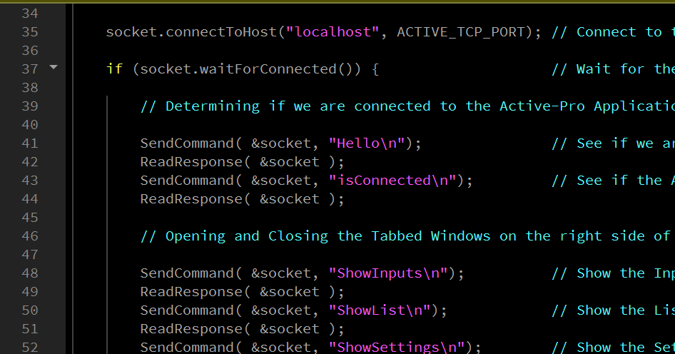
The following C/Qt example demonstrates connecting to the TCP socket and sending commands:
#include <QTcpSocket>

#define ACTIVE_TCP_PORT 37800

void SendCommand(QTcpSocket *socket, const char *str)
{
    socket->write(str);
    socket->waitForBytesWritten();
}

QString ReadResponse(QTcpSocket *socket)
{
    if (!socket->canReadLine())
        socket->waitForReadyRead(1000);
    return socket->readLine();
}

int main(int argc, char const* argv[])
{
    QTcpSocket socket;
    socket.connectToHost("localhost", ACTIVE_TCP_PORT);

    if (socket.waitForConnected()) {
        SendCommand(&socket, "Hello\n");
        ReadResponse(&socket); // -> HELLO

        SendCommand(&socket, "isConnected\n");
        ReadResponse(&socket); // -> YES or NO

        SendCommand(&socket, "STARTCAPTURE\n");
        ReadResponse(&socket); // -> OK

        SendCommand(&socket, "GetLogic\n");
        ReadResponse(&socket); // -> 0-255

        SendCommand(&socket, "STOPCAPTURE\n");
        ReadResponse(&socket); // -> OK

        SendCommand(&socket, "SaveCapture C:\\captures\\test.active\n");
        ReadResponse(&socket); // -> OK

        socket.close();
    }
}
See Also
The MCP Server wraps the full Automation API as typed tools for AI assistants. If your goal is letting Claude Desktop run test sequences or analyze captures in plain English rather than writing socket code, the MCP Server is the faster path.