
PacketPresenter
PacketPresenter
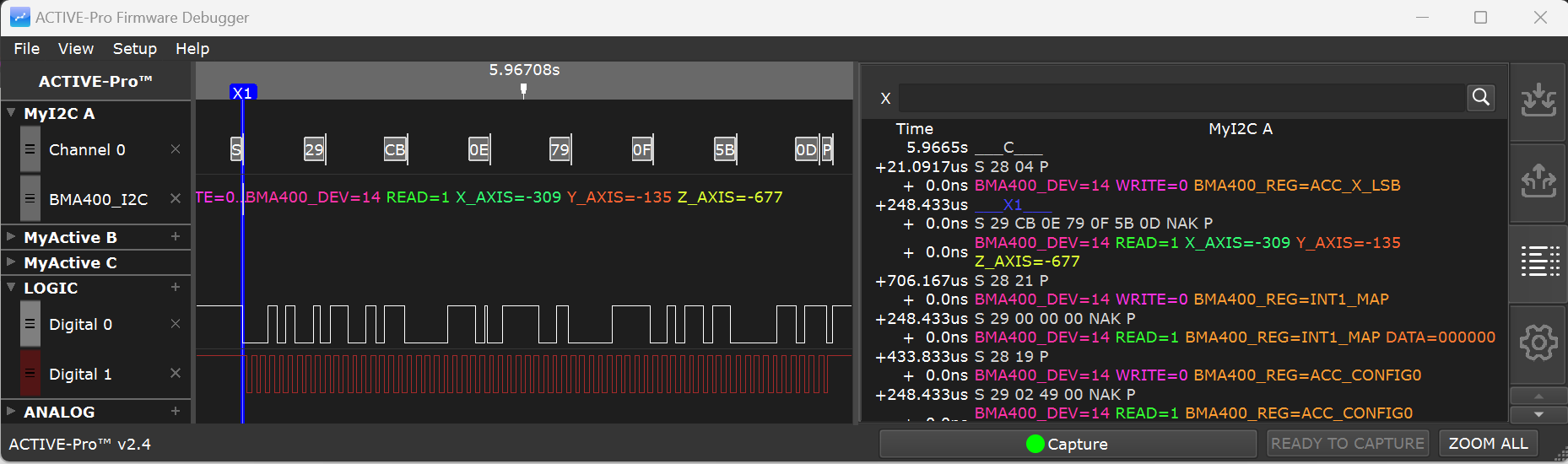
The PacketPresenter (PP) engine adds an application-layer decoding pass on top of any hardware, software, or Custom Decoder. Where the lower-layer decoder produces raw bytes, the PacketPresenter interprets those bytes as structured packets with named fields, turning 0x28 0x03 0x00 0xFF into something like WRITE addr=0x28 reg=CMD val=0xFF.
You define your packet structure in a plain text definition file using a simple scripting language. The PP engine runs your definition against the byte stream in real time during capture, or reruns it on existing capture data whenever you save a new definition or press APPLY CHANGES.
Why Use PacketPresenter?
The hardware decoder (or your Custom Decoder) handles framing, it knows where bytes start and end on the bus. The PacketPresenter handles meaning, it knows what those bytes represent in your application's protocol. If you are debugging an I2C device, the I2C decoder shows you raw bytes; the PacketPresenter can show you field names, register values in engineering units, and state machine names.
If your firmware uses a custom packet protocol over UART, SPI, or any other transport, the PacketPresenter is how you make that protocol visible in the waveform display. You can also point it at the byte stream emitted by a Python Custom Decoder, useful when your Custom Decoder turns an unusual physical-layer signal into bytes and you want PP to add field-level meaning on top.
Enabling PacketPresenter
PacketPresenter is enabled automatically per port based on the selected decoder mode. There is no user-facing enable checkbox: when you pick a decoder mode that supports PP, the engine is enabled for that port; when you pick a mode that does not, it is disabled.
When the current decoder mode supports PP, the Edit Packet Presenter button row becomes visible next to that port in the Inputs tab. When the decoder mode does not support PP, the row is hidden.
When PP becomes enabled on a port, the application automatically loads a default PP definition appropriate for the selected decoder mode (I2C default, UART default, SPI default, etc.) if one is available.
Default PP Definitions
The application ships with default definitions for common protocols:
- UART Default Packet Format
- UART 9-bit Default Packet Format
- I2C Default Packet Format
- SPI Default Packet Format
- 1-Wire Default Packet Format
- CAN Default Packet Format
- CHSI Default Packet Format
- MDIO Default Packet Format
- DS101 Default Packet Format
- LIN Default Packet Format
The default for I2C, for example, shows each transaction as W addr data... or R addr data..., which is immediately readable without any customization. Start with the default and customize it to match your specific device.
Editing a PP Definition
Click the Edit Packet Presenter button in the Inputs tab to open the PacketPresenter Editor dialog.
The editor shows the current definition text. The dialog has only two buttons across the bottom:
| Button | Action | |
|---|---|---|
| Save | Stores the edited definition and marks a pending change (lights the APPLY CHANGES button); it does not reprocess on its own | |
| Cancel | Discards all changes and closes the dialog |
Editing a Packet Presenter now works exactly like editing a Custom Decoder: Save records your new definition and lights the APPLY CHANGES button in the status bar, but nothing is reprocessed until you press it. This lets you batch several edits (Packet Presenter, Custom Decoder, trigger) into one reprocess instead of firing a fresh — and on a large capture, minutes-long — pass after every save. Press APPLY CHANGES when you are ready, and the waveform updates with the newly decoded output.
No Import / Export / Help buttons: the current PacketPresenter Editor has no buttons to import a
.ppfile from disk, export the current text to disk, or open in-line help. To share a PP definition with someone, copy the text out of the editor with standard clipboard shortcuts, or share the.activecapture that uses it (PP definitions travel with the capture file).
Viewing the PacketPresenter Output
The PacketPresenter output is shown in a waveline below the raw bus decode waveline, with the title defined in the [Protocol] name field. Clicking a PP block scrolls the List tab to that packet's rows.
Cursor Synchronization
The PacketPresenter output and waveform display are synchronized using cursors. You can place cursors by clicking with the left or right mouse buttons over a packet in the waveform, cursors are placed at the beginning of packets. Conversely, if you place X1 and X2 cursors in the waveform display, the PacketPresenter list scrolls to show that location.
PP Definition File Format
Each PacketPresenter Definition file is a plain text file divided into labeled sections. The file is case-insensitive for section names and keywords. Comments begin with // and continue to the end of the line.
Constants
Constants can be expressed as decimal, hex, or binary:
- Decimal:
16 - Hex:
10h - Binary:
10000b
Gain and offset values in the Fields section are always in decimal and can contain decimal places.
File Structure
A definition file contains one or more [Protocol] sections:
[Protocol]
    name = ProtocolName
    [Packet]
    [Start]
    ... // How does a packet start?
    [End]
    ... // How does a packet end?
    [Decode]
    ... // What decoding needs to be done?
    [Fields]
    ... // Field definitions
The first [Protocol] in the file is the top-level protocol that receives the raw byte stream from the lower-layer decoder.
File Limits
| Parameter | Limit | |
|---|---|---|
| File size | 100 KB maximum | |
| Protocols per definition | 7 | |
| Field lines per protocol | 1024 | |
| Fields per field line | 128 | |
| Lookup tables | 64 per protocol | |
| Entries per lookup table | 256 | |
| Decoder substitutions | 256 per protocol |
[Protocol] Section
Names the protocol and sets the basic parsing mode.
[Protocol]
Name = MyProtocol
ProcessBy = Byte| Key | Values | Description | ||
|---|---|---|---|---|
Name |
String | Protocol name shown in the waveform | ||
ProcessBy |
Byte or Bit |
Parse the stream one byte at a time, or one bit at a time |
[Packet] Section
Defines what marks the beginning and end of each packet. Contains [Start], [End], and optionally [Decode] subsections.
Packet Start Types
| Start type | Description | |
|---|---|---|
type = Next |
Every byte starts a new packet immediately | |
type = Value + value = 0xXX |
Packet starts when a specific byte value is received | |
type = Signal + signal = N + level = 1 |
Packet starts on a specific signal level | |
type = Event + event = N |
Packet starts when the decoder produces a specific bus event |
Packet End Types
| End type | Description | |
|---|---|---|
type = Next |
Packet ends when the next packet's start condition is detected. Add EXCLUDE to leave the end byte on the stream for the next packet. |
|
type = Value + value = 0xXX |
Packet ends when a specific byte value is received. Add EXCLUDE to leave that byte available for the next packet. |
|
type = Timeout + timeout = N |
Packet ends when no new bytes arrive for N microseconds | |
type = Length + ByteLength = N or BitLength = N |
Packet ends after exactly N bytes (or bits). Length can also be a field name with optional arithmetic: ByteLength = fieldname * 2 + 2 |
|
type = Event + event = N |
Packet ends when the decoder produces a specific bus event |
Bus Events by Bus Type
| Bus Type | Event Value | Meaning | ||
|---|---|---|---|---|
| UART | 1 | Parity Error | ||
| I2C | 1 | Start Bit | ||
| I2C | 2 | Stop Bit | ||
| I2C | 4 | ACK | ||
| I2C | 8 | NACK | ||
| SPI | 1 | SS Active | ||
| SPI | 2 | SS Inactive | ||
| Custom Decoder | 2 | SAMPLE_PACKET_START (set by the script via append(..., sample_type=2)) |
||
| Custom Decoder | 3 | SAMPLE_PACKET_END (set by the script via append(..., sample_type=3)) |
Multiple event values can be ORed together: event = 3 means either event 1 or event 2.
CHANNELX, CHANNELY, CHANNELXorY
For buses with multiple data signals (such as SPI with MOSI and MISO, or a Custom Decoder that emits both DATA and DATA_ALT rows), specify which channel a start or end condition applies to using channelX, channelY, or channelXorY in the [Start] or [End] section.
[Decode] Section (Optional)
Specifies encoding transforms to remove from the packet before field parsing.
| Transform | Description | |
|---|---|---|
NRZI |
Non-Return-to-Zero Inverted decoding | |
Manchester |
Manchester encoding removal | |
INVERT |
Bit inversion | |
ZBI5 |
Zero Bit Insertion removal (removes the 0 added after 5 consecutive 1s) | |
ZBI6 |
Zero Bit Insertion removal (removes the 0 added after 6 consecutive 1s) | |
| Substitutions | Byte sequence replacement (see below) |
Multiple decoders can be used and are processed in the order listed.
Substitutions
Substitutions allow a sequence of bytes (up to 3) to be replaced with a different set (same size or fewer bytes). No spaces allowed in the values.
[1]=[2] // Replace all 0x01 bytes with 0x02
[1][2]=[3] // Replace the sequence 0x01 0x02 with 0x03
[7Dh][5Eh]=[7Eh] // HDLC byte unstuffing example
[7Dh][5Dh]=[7Dh]
[Fields] Section
Defines the named fields within each packet. Fields are parsed in order.
Field Lines
Each Fields line defines one complete packet format from start to end:
Fields Field1, Field2, ..., FieldNYou can also insert a literal string to be printed at a specific position using the $ prefix:
Fields Field1, $MyString, Field2Conditional vs. Unconditional Field Lines
Any unconditional Field Line (no =value conditions) generates an output line for every packet. Conditional Field Lines are only processed if specific field values match. A Conditional Field Line that evaluates to false is skipped. List conditional lines first, followed by an unconditional catch-all.
Field Format
FieldName.InputModifiers[.OutputModifiers]FieldName cannot contain spaces, commas, semicolons, brackets, dollar signs, periods, or quotes.
Input Modifiers
| Modifier | Description | |
|---|---|---|
8 (or any number) |
Number of bits in the field | |
N |
Variable-length field, consumes all remaining bytes in the packet for this channel | |
0 |
Zero-length: use the most recent value of this field name from a previous packet (for stateful protocols) | |
m or M |
Most-significant bit first (MSB first), default | |
l or L |
Least-significant bit first (LSB first, bit-reversed) | |
B |
Invert byte order (big-endian multi-byte fields) | |
X |
Data is on Channel X | |
Y |
Data is on Channel Y | |
=value |
Conditional: this field MUST equal value for this line to be processed |
Output Modifiers
| Modifier | Description | |
|---|---|---|
I or i |
Ignore, decode but do not print | |
H or h |
Hexadecimal output | |
D or d |
Decimal output (unsigned) | |
S or s |
Decimal output (signed, sign-extend from MSBit) | |
SN |
Decimal output (signed, sign-extend from bit N) | |
B or b |
Binary output | |
A or a |
ASCII character output | |
L |
String lookup in a matching Lookup table | |
TF |
True (nonzero) or False (zero) | |
TFT |
Show only if True (nonzero) | |
TFF |
Show only if False (zero) | |
*Value |
Multiply the output value by Value before display | |
/Value |
Divide the output value by Value before display | |
+Value |
Add Value to the output value before display | |
-Value |
Subtract Value from the output value before display | |
$string |
Append a string after the value (or replace it if I is also set). Must be last in the field. |
Example, displaying temperature in degrees Celsius from a TMP117:
TempRaw, 16.M, .d*7.8125$mCThis reads a 16-bit big-endian value, multiplies by 7.8125 (the TMP117 LSB weight in millidegrees), and appends "mC".
Bus Events Within a Field Line
To require a specific bus event at a specific position within a packet's field sequence, place the event value in brackets:
Fields Field1, [1], Field2 // I2C Start Bit must appear between Field1 and Field2
Fields Field1, [!1], Field2 // I2C Start Bit must NOT appear between Field1 and Field2
Lookup Tables
Lookup tables map numeric field values to human-readable strings. Define them after the [Fields] section.
[StateTable]
0 = Idle
1 = Running
2 = Fault
255 = Unknown
Reference the table in a field definition with .L=StateTable. When a field value matches an entry, the string is shown instead of the number. If a value is not in the table, the numeric value is shown as a fallback.
Lookup tables are scoped to the [Protocol] section they are defined in.
Multi-Protocol Definitions (Layered Protocols)
A single .pp definition file can contain up to 7 [Protocol] sections. This allows handling of multi-layer protocols where a field from one layer is the input data stream for another layer. To route a field to a child protocol, name the field the same as the child protocol's name.
[Protocol]
name = Layer1
[Fields]
Fields Command.4=0.h, Address.8.h
Fields Command.4=1.h, Layer2.48.h // Route to Layer2 protocol

[Protocol]
name = Layer2
[Fields]
Fields L2Command.4=0.h, RSSI.8.d
Fields L2Command.4=1.h, QoS.16.d
Debug Mode
To troubleshoot a PP definition, add a [DEBUG] section with DebugOn to any [Protocol] section:
[Protocol]
name = MyProtocol

[DEBUG]
DebugOn // Comment out to disable

[Packet]
...
When debug mode is on, each packet is output twice in its raw form, showing the raw bus data values and events before and after decoding, followed by the normal PacketPresenter output. This lets you verify that the packet boundaries and field values are being parsed as expected.
Error Handling
If the PP definition contains a syntax error, the application shows a Packet Definition File Error dialog with a description of the problem. Click OK, reopen the PacketPresenter Editor for the affected port, fix the issue, and click Save to rerun.
Common mistakes:
- Missing
[Protocol],[Packet], or[Fields]sections - Referencing a lookup table name that is not defined in the file
- Specifying a bit width of 0 or a negative value
Example: Simple UART Protocol
[Protocol]
Name = MyDevice
ProcessBy = Byte

[Packet]
[Start]
Type = Value
Value = 0xAA
[End]
Type = Length
Value = 4

[Fields]
Fields Sync.8.h, Command.8.L, Data.8.h, Checksum.8.h

[CmdTable]
[01h]=$START
[02h]=$STOP
[03h]=$RESET
[10h]=$READ_STATUS
[11h]=$WRITE_CONFIG
With this definition, every matching packet shows something like:
Sync=0xAA Command=START Data=0x00 Checksum=0x03
Example: I2C Generic Decoder
[Protocol]
name = I2C_Packets
bytewise

[Packet]
[Start]
type = event
event = 1 // Start bit
[End]
type = event
event = 2 // Stop Bit

[Fields]
Fields dev.7m.h, RW.1=0.L, add.16m.h, [1], dev.7m.h, RW.1=1.L, data.Nm.h // Read with 16-bit address
Fields dev.7m.h, RW.1=0.L, add.8m.h, [1], dev.7m.h, RW.1=1.L, data.Nm.h // Read with 8-bit address
Fields dev.7m.h, RW.1=1.L, data.Nm.h // Read Transaction
Fields dev.7m.h, RW.1=0.L, add.8m.h, data.Nm.h // Write Transaction

Lookup RW
[0]=$Write
[1]=$Read
PacketPresenter Definition Library
Contribute your own definitions by sending them to support@activefirmwaretools.com. The following definitions ship with the application or are available as examples.
- UART ASCII Text (CR terminated)
- UART ASCII Text (LF terminated)
- UART ASCII Text (NULL terminated)
- UART Binary Data (Timeout Terminated)
- I2C Generic Decoder
- SPI Generic Decoder
- TMP117 Temperature Sensor
- BMA400 Accelerometer
- MDIO
- UART 9-bit
- DS101
- CHSI
- 1-Wire