
Custom Decoders
Custom Decoders
What a Custom Decoder Is
A Custom Decoder is a small Python script you can attach to one of the four device ports (A, B, C, D) to turn captured digital and analog samples into annotation rows of your own design. The script runs after capture has stopped, walks the captured buffer end-to-end, and emits decoded text and numeric values that appear in the waveform display, the decode list, the PacketPresenter, the trigger system, and the .aft AI export, exactly like a built-in decoder.
Custom Decoders are aimed at protocols that the built-in hardware and software decoders do not cover, and at one-off measurement scripts (bit-bang waveforms, mixed analog/digital state machines, encoder counters, custom serial framings). You can ship them with your project, the script is saved inside the .active capture file, so anyone who opens the capture sees exactly what you saw.
Each port hosts a base decoder and can optionally stack additional Python decoders on top of it, each consuming the output of the one below (see "Stacking Decoders"). With four ports, four independent decoder stacks can run against the same capture, executing in slot order A → B → C → D.
Built-in Decoders vs. My Decoder Library
There are two kinds of Custom Decoder, and the application keeps them strictly apart so that updates can never collide with your work:
- Built-in decoders ship with the application (UART, I²C, SPI, I³C, CAN, LIN, Modbus RTU, PWM, Manchester, DMX-512, MIDI, HD44780, RS-232/485, 1-Wire, PS/2, HART, I²S, SMBus, PMBus, QSPI, RGMII, WS2812, Quadrature, DHT, 4-20 mA Loop, SWD, JTAG, and more, plus a few
test_decoder_*examples). They live inside the application alongside theactive_pro.pyruntime, are read-only, and update automatically with the app — exactly like the.exe. When we fix a bug in a built-in decoder or in the runtime, you get the fix the moment you install the new build. You never have to do anything, and there is nothing to go stale. - My Decoder Library is your own collection — the decoders you create. They live in the My Decoder Library folder, which the application never writes to. Nothing you put there is ever overwritten, on any launch, ever.
The picker shows both in one list with a Type column that reads Built-in or My Library, so you always know which is which.
The My Decoder Library Folder
By default the My Decoder Library folder is <working directory>/decoders. The working directory is the one shown on the Capture File Location row in the Settings panel. The folder is shared across all four pods - it is at the bare working directory, not nested under a per-pod sub-folder. It starts empty; built-ins are not copied into it.
How to customize a built-in decoder
Built-ins are read-only, but you don't have to do anything special to start from one — just open it, edit, and save. The full sequence, from an unconfigured port to a running custom decoder of your own:
- On the port you want (A, B, C, or D), open the Bus Decoder dropdown and, under Post-Capture Python Decode, choose CHOOSE CUSTOM DECODER…. The Decoder Picker opens.
- Select the built-in you want to start from — its Type column reads Built-in (for example,
I2C_Decoder) — and click Select. It is now attached to the port and the dropdown shows its name. - Click the pencil icon next to the dropdown. The decoder's source opens in the editor.
- Edit the script, then click Save to My Decoder Library. Because the original is a built-in (read-only), a save dialog opens in your My Decoder Library folder with the name filled in — keep it or change it, then save. Your copy is written there, the port immediately switches to running it, and it appears in the picker under My Decoder Library.
- If your decoder declares
PARAM:lines, click the gear icon next to the dropdown to set its parameters. - Click APPLY CHANGES on the bottom button bar to run it against the current capture.
Your copy is yours forever and is never overwritten by an update, while the built-in you started from keeps getting our fixes. You can also start from scratch with New... in the picker (a blank decoder from the template) instead of steps 2–4. The only thing you cannot do is change a built-in in place — Save to My Decoder Library on a built-in always writes a copy instead.
Just trying something on one capture? Use Use This Decoder instead of Save to My Decoder Library. It runs your edited script on the port for the current capture without writing any file (the built-in or your original file is left alone). The pencil is always available while a Custom Decoder is attached.
Editing one of your decoders? Pressing Save to My Decoder Library writes straight back to its file (no name prompt).
Pointing at a different folder
Your decoder folder is configured in Settings → Decoder Directory:
- Follow working directory checkbox (default on), the decoder folder tracks the working directory.
- Decoder folder path field, only editable when "Follow working directory" is off. Browse to any folder on disk. The application reads
.pyfiles from there. - Reset button, restores "Follow working directory" and clears the custom path.
The setting is per-user (stored in your OS-level application settings), not per-pod, so all four pods share the same decoder folder. (Built-in decoders come from the application regardless of this setting.)
Opening the folder
There are four ways to open your My Decoder Library folder in your system file explorer:
- Settings tab → Open My Decoder Library button (under My Decoder Library Folder).
- File menu → Open My Decoder Library.
- Decoder Picker → Open My Decoder Library button.
- Clicking the folder path link in the Decoder Picker's header banner.
Attaching a Custom Decoder to a Port
The Bus Decoder dropdown on each port (the same dropdown you use to pick UART, SPI, I²C, etc.) groups its entries into three sections:
- Real-Time Hardware Decode - runs on the FPGA inside the pod during capture.
- Real-Time Software Decode - runs on the host during capture.
- Post-Capture Python Decode - Custom Decoders. Runs after capture stops.
The Post-Capture Python Decode section contains a single entry: CHOOSE CUSTOM DECODER…. Selecting it opens the Decoder Picker. Once you pick a decoder, the dropdown's collapsed text becomes the picked decoder's filename so you can tell at a glance which decoder each port is running. If you reopen the dropdown, the "CHOOSE CUSTOM DECODER…" prompt is shown there instead of the filename, so the popup is always an action prompt, not a status indicator.
Switching a port away from a Custom Decoder (back to UART, OFF, etc.) clears that port's script, parameters, and display name. To get them back you have to re-select the decoder from the picker.
The Decoder Picker
The picker is a single dialog that lists both the built-in decoders (served from the application) and your My Decoder Library (every .py in your My Decoder Library folder with a valid DECODER_MYNAME line). The two lists are independent: a built-in and one of your decoders may share a name (e.g. two CAN_Decoder entries) and both are shown, each tagged in the Type column, so you can pick whichever one you want. Nothing is ever hidden.
Header banner
Across the top is a label that shows the exact folder being read: My Decoder Library folder: <path>. The path is a clickable link that opens that folder in your file explorer. This is your My Decoder Library folder; built-ins come from the application and are not in it.
Filter
Below the banner is a search box labeled Filter:. Typing in it filters the table to rows that match what you typed in any column (Name, Type, or Description), case-insensitive.
Columns
The table has five columns:
- Name - the filename without
.py. This is what the application uses internally as the decoder's identity, and what appears in the port's Bus Decoder dropdown after you pick it. - Type - Built-in (ships with the app, read-only, updates automatically) or My Library (you added it; the app never overwrites it).
- Description - the first free-form comment line at the top of the script (after
DECODER_MYNAMEand anyPARAMlines). One sentence is best, multi-line descriptions get truncated. - Date Modified - the file's last-modified time.
- Size - the file size, in B, KB, or MB.
Click a column header to sort - sorting by Type groups your decoders apart from the built-ins. The Description column is the elastic one and grows as you resize the dialog.
Live refresh
The picker watches your My Decoder Library folder while it is open. If you add, rename, delete, or edit any .py file in it (in Explorer or any other editor), the table refreshes within about a quarter-second without losing the row you had selected.
Buttons
- Open My Decoder Library - opens your My Decoder Library folder in your file explorer. Same as the link in the banner.
- New... - prompts for a new decoder name, creates
<name>.pyin your My Decoder Library folder from the built-in template, and opens it in your registered Python editor. On Windows the file is opened with the system's "edit" verb (Notepad, VS Code, Notepad++, whatever you have set), not the launcher, so the file does not execute. On macOS/Linux the containing folder opens because there is no portable equivalent of the Windows "edit" verb; pick your editor manually. - Select - accepts the picker with the currently highlighted row and attaches that decoder to the port. Disabled until something is selected. Double-clicking a row is equivalent. (To customize a built-in, Select it, then edit it with the pencil and click Save to My Decoder Library. See "How to customize a built-in decoder.")
- Cancel - closes the picker. The port reverts to whatever decoder it had before.
Picking the same decoder twice
If you reopen the picker on a port that already has a decoder loaded, and pick the same one again, nothing reprocesses. The application only marks "changes pending" when the decoder actually changes.
Configuring Parameters: the Gear Button
Once a port has a Custom Decoder attached, two small buttons appear next to its Bus Decoder dropdown:
- A gear icon (parameters)
- A pencil icon (script editor)
The gear is only enabled if the script declares one or more PARAM: lines (see the Authoring section). Clicking it opens the parameter dialog, which is built dynamically from those lines.
The dialog title is Configure <decoder name>. Each parameter appears as one labeled row. The control type depends on the parameter's declared type:
select- drop-down list with one option per comma-separated value.int- integer spin box. If the script gives amin,maxrange, the spin box clamps to that range; otherwise the full 32-bit integer range is allowed.float- floating-point spin box with 6 decimal places. Samemin,maxrule asint.bool- checkbox.string- free-text field.digital_channel- spin box clamped to 0-7. Names a digital channel the decoder will read.analog_channel- spin box clamped to 1-8. Names an analog channel the decoder will read. Active-Pro has channels 1-4, Active-Pro Ultra has 1-8, the Active Debugger has no analog channels. The spin box does not gate the range by connected model, so you are responsible for not picking a channel your pod does not have.
Save stores the new parameter values into the port's configuration and marks changes pending. Cancel discards your edits.
Automatic channel activation
digital_channel and analog_channel parameters do more than just pass a number to the script. As soon as you save the dialog, the named channels are forced ON for capture, even if you had previously disabled them on the Inputs tab. This is also true at attach time: when you pick a decoder, each digital_channel parameter is seeded so the port's home pair is used first (A → channels 0/1, B → 2/3, C → 4/5, D → 6/7), with any further digital_channel parameters continuing modulo 8. analog_channel parameters keep the script's default.
Channel conflict warning
When you save the gear dialog, the application checks whether the channels this decoder now claims overlap with channels claimed by another port, a Custom Decoder on another port, or a built-in decoder whose protocol uses those channels.
If there is a collision, a modal warning lists each conflict, e.g.:
Port C's decoder is using channels already in use by:
Port A (UART): logic 0 Port B (My SPI): logic 2, analog CH1
Your change is saved as-is. No other ports are modified. Reopen the gear dialog to pick different channels if needed. Built-in hardware decoders on other ports do reserve their channels for conflict detection (the FPGA taps those lines whether your script wants them or not), so they participate in the warning even though they do not appear on the Inputs tab as "forced on".
Editing the Script: the Pencil Button
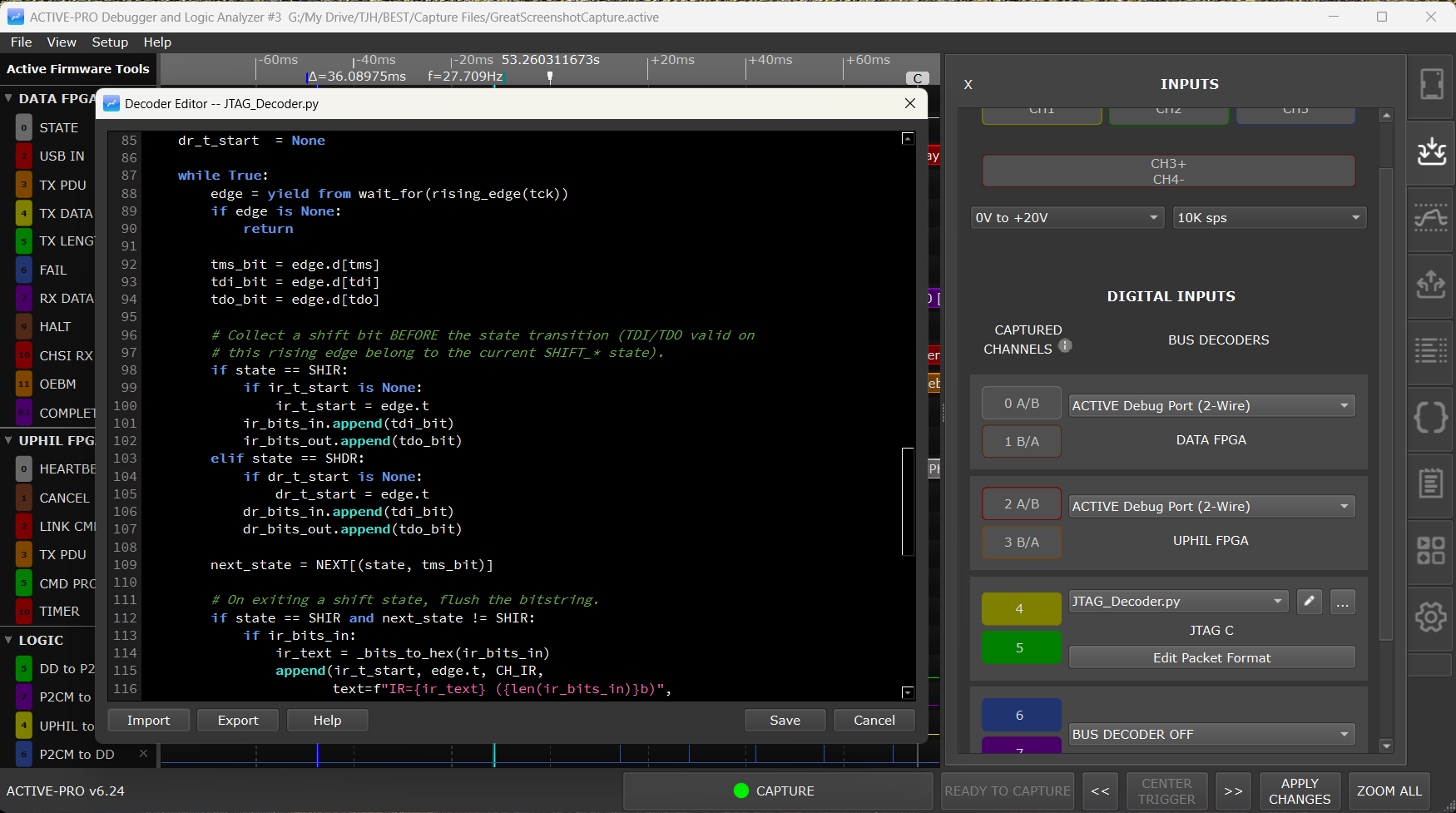
The pencil opens the in-application script editor for that port's decoder. It is a black-background code editor with:
- Line numbers in a gutter on the left. Python tracebacks identify failures by line number, so this lets you jump straight to the line the traceback mentions.
- Python syntax highlighting - keywords, strings, comments, numbers.
- Monospace font - uses the same source-code font as the PacketPresenter editor.
- 4-space tab stops.
- Current-line highlight - a subtle dark-grey band on the line your cursor is on.
The title bar reads Decoder Editor -- <decoder name>.py so you cannot lose track of which port's script you are editing.
Buttons across the bottom
- Use This Decoder (the default) - apply the current script to this port for the current capture and close. The text is pinned into the
.activelike any attached decoder, but no file is written — ideal for a quick, one-off tweak or for accepting a built-in as-is. The change is marked pending; click APPLY CHANGES to reprocess. - Save to My Decoder Library - write the script to a
.pyfile in your My Decoder Library folder, attach it to the port, and close (save, use, and close in one step). Use this when you want a reusable decoder of your own.- Editing a built-in (read-only): a save dialog opens in My Decoder Library with the name pre-filled — keep it or rename — and your copy is created there. The built-in is never modified.
- Editing one of your own decoders: it saves straight back to its file (no prompt).
- Help - opens the online manual page for Custom Decoders in your browser.
- Cancel - closes the editor without applying or saving anything.
Use This Decoder vs. Save to My Decoder Library
Both run your edited decoder on the port; the difference is whether a reusable file is created:
- Use This Decoder keeps the edit with the capture only (pinned into the
.active). The on-disk decoder — built-in or your own file — is left untouched. Perfect for experimenting on one capture. - Save to My Decoder Library also writes the script as a file in My Decoder Library, so it shows in the picker and is available to other ports and future sessions. You can never overwrite a built-in this way — saving a built-in always creates your own copy (named however you like).
Either way, because the script text is pinned into the .active (see "Persistence"), a saved capture replays exactly what ran, independently of the files in My Decoder Library.
Running the Decoder: APPLY CHANGES
Custom Decoders run after capture has stopped, not during capture. This is a deliberate design choice: it lets the decoder freely walk forward and backward through the data, lets you re-run a decoder with different parameters against the same capture without re-capturing, and means a slow decoder cannot drop samples.
The runner is triggered in three ways:
- At the end of every live capture - when STOP is pressed (or the buffer fills, or the trigger's post-trigger condition is met), the decoder pipeline runs as part of post-capture processing.
- When opening a saved
.activefile - if the file contains Custom Decoder scripts, they re-run against the loaded capture. - The APPLY CHANGES button at the bottom of the window - re-runs the pipeline against the current capture, picking up any decoder script edits, gear-dialog parameter changes, picker re-selections, Packet Presenter definition edits, or trigger setting changes you have made since the last run. The button is enabled when there are pending changes and no capture is in progress; if you are still capturing, click STOP first.
Nothing reprocesses on its own. Editing a Custom Decoder or a Packet Presenter just marks a pending change and lights APPLY CHANGES, so several edits batch into a single reprocess instead of firing one (and on a large capture, minutes-long) pass per edit. The button's tooltip tells you which kind of pass is pending before you click.
The full pipeline order is:
- Custom Decoders - port A → B → C → D, one at a time. Within a port, the base decoder runs first, then each stacked layer in order, bottom to top (see "Stacking Decoders").
- Packet Presenters - each port's PacketPresenter runs against the output of that port's top decoder layer.
- Trigger Search - re-scans for trigger matches across the now-current channel data.
Trigger-only fast path: if the only thing you changed since the last apply is a trigger setting, APPLY CHANGES skips stages 1 and 2 and re-runs just the Trigger Search against the existing decoded data. Trigger tuning stays instant; the full (potentially minutes-long) decode + Packet Presenter pass only runs when you have actually changed a decoder or Packet Presenter.
Status bar feedback
While the decoders run, the status bar shows live progress:
Processing Custom Decoder: My SPI — 37% — 1284 records
The percentage is the decoder's progress through the captured logic and analog buffers. "Records" is how many annotations the Python script has emitted so far. After each decoder completes you see Custom Decoder 'X' complete., and after all decoders finish, Custom Decoders complete..
Cancelling
Hitting the CAPTURE button during a post-capture decoder run cancels the remainder. The decoder currently running is killed; any annotations it had already produced stay in the display. Decoders queued after it are skipped.
Stacking Decoders
A single port can run an ordered stack of decoders, where each layer consumes the decoded output of the layer below it instead of the raw signal. This lets you build a protocol up in tiers - decode the wire once, then add application meaning on top - without one giant script.
- Layer 0, the base, is the port's normal decoder: a built-in hardware or software protocol (I²C, SPI, UART, CAN, …) or a Custom Python decoder.
- Layers 1 and up are Custom Python decoders that read the layer below. A port holds a base plus up to three stacked layers (four total).
Each layer's output appears on its own waveform rows and feeds the next layer up. The PacketPresenter sits at the very top and frames whatever the top layer emits.
Example stacks:
I²C → SMBus → PMBus,CAN → J1939 → your app layer, or your ownUART → framing → message decode. The base does the wire-level work (built-in and fast); each Python layer adds one level of interpretation.
Which bases can host a stack
Stacking is offered on any port whose base produces byte/event data - every built-in hardware or software protocol, and any Custom Decoder. The Active Debug Port modes (2-Wire, 1-Wire, SWV) and the EE101 modes are the exception: they emit text/value streams rather than a byte stream, so they cannot host a stack, and no flow arrow or + Add Stacked Decoder row appears for them.
Building a stack in the Inputs tab
Once a port has a base decoder, a flow of rows appears beneath it:
- A ↳ flow arrow runs from each layer into the one above it, so the stack reads top-to-bottom as "this feeds that."
- Each stacked layer is a row showing the decoder name (or (pick decoder...) until you choose one), plus the same gear (parameters) and pencil (edit script) buttons as a base custom decoder, and an ✕ to remove that layer.
- A + Add Stacked Decoder row sits at the bottom of the stack whenever there is room (fewer than three layers). Click it to open the Decoder Picker and choose the next layer; it attaches above the current top.
- The Edit Packet Presenter row sits one step past the top layer, because the PacketPresenter consumes the top layer's output.
Stacked layers are chosen from the same Decoder Picker as a base and edited with the same script editor; everything under "The Decoder Picker," "Configuring Parameters," and "Editing the Script" applies to each layer. Removing a layer with ✕ drops it; the remaining layers stay contiguous.
Reading the layer below: source_events()
A stacked Custom Decoder reads the layer below as a stream of finished events instead of raw signal. A minimal "invert every byte" layer:
from active_pro import append, source_events, SAMPLE_DATA

def decode(params):
    if False:
        yield                                    # makes decode() a generator
    for ev in source_events():                   # events from the layer below, in time order
        b = (~ev.data) & 0xFF
        append(ev.t_start, ev.t_end, 0,
               text=f"0x{b:02X}", sample_type=SAMPLE_DATA, data=b, num_bits=8)
source_events() yields the lower layer's annotations as Event objects, already finished and sorted in time:
ev.t_start,ev.t_end- the event's timestamps in seconds.ev.channel- the source row, 0-based relative to the layer below (its slot offset is already removed).ev.data- the 32-bitdatavalue the lower layer emitted.ev.text- the lower layer's annotation text.ev.sample_type-SAMPLE_DATA,SAMPLE_DATA_ALT,SAMPLE_PACKET_START, orSAMPLE_PACKET_END, so you can see the packet framing from below.ev.color- the lower layer's color word.
Two optional filters narrow what you iterate:
for ev in source_events(channel=0):               # only row 0 of the layer below
for ev in source_events(sample_type=SAMPLE_DATA):  # skip START/STOP framing markers
Because the lower layer has already finished when your layer runs, the whole event stream is available in time order - you are not fed chunks.
Stacked layers are still hybrid decoders. A stacked layer keeps full access to the raw capture: you can mix
wait_for/wait_timeover the physical LOGIC and ANALOG channels withsource_events()in the samedecode(). That lets a layer correlate a decoded event with the analog level at that instant, for example.
Pure consumers need a generator marker. A layer that only iterates
source_events()and never calls await_*still must be a generator (the runtime requires it). Add aif False: yieldline, as in the example above; the loop body runs to completion in one pass.
What the top layer feeds the PacketPresenter
The PacketPresenter always consumes the top layer of the stack. Emit SAMPLE_PACKET_START / SAMPLE_PACKET_END framing and set num_bits on your data values in the top layer to frame packets, exactly as a single-layer decoder does for its PacketPresenter. See the PacketPresenter chapter.
Stacking examples to start from
Several bundled decoders exist specifically to demonstrate and test stacking. Open them from the picker (Type = Built-in), Save-to-My-Library a copy, and adapt:
- Edge Marker (base) and Every 4th - the original minimal stack demo.
- Packet Maker (base) - emits clean
START … data … STOPpackets so you have a deterministic source to stack onto. - Passthrough, Invert Bytes, Packet Sum, Packet Byte Count - stacked layers that re-emit, transform, or aggregate the layer below, each forwarding the Start/data/Stop framing to the PacketPresenter.
Driving Custom Decoders from a Script or AI Assistant
The Automation API and the MCP server do not expose any commands for attaching a Custom Decoder, setting its parameters, or editing its script. Custom Decoder selection and configuration is a GUI-only operation. This is deliberate: decoder scripts and gear-dialog parameters are tightly coupled, and the safe way to apply them from a script is to load a known-good configuration that already has them set.
Recommended workflow
- Configure in the GUI. Pick the Custom Decoder mode for the desired port, choose the script in the decoder picker, set parameters in the gear dialog, and configure any channel labels, units, threshold, trigger, or buffer settings you want to apply alongside.
- Save a configuration file. Use File → Save Configuration (or the
SaveConfiguration <path>API command) to capture the current settings to a.activeconfiguration file. Custom Decoder selection, parameters, and the script filename are included. - Drive from your script. From a Python script, an AI assistant, or any other automation client, send
OpenConfiguration <path>to load that configuration on the running application. If a capture is already loaded and you want to reprocess it through the freshly loaded decoders, sendApplyChangesafterOpenConfiguration. - Run captures normally.
StartCaptureandStopCapturework as usual; the decoder pipeline runs at the end of every capture using whatever was loaded by step 3.
Why no API for attach / parameters / script
A Custom Decoder is a Python file on disk, plus the gear-dialog parameter values, plus the port assignment. Each piece has to match the others for the decoder to produce correct output. Exposing setters for each piece individually would invite scripts that set them in inconsistent combinations. Loading a configuration file applies the whole set atomically.
If you need to change one parameter from a script, edit the saved configuration file directly with a text editor (or have the AI edit it), then OpenConfiguration to reload. The configuration file is a plain INI format.
What you can do from a script
Around the Custom Decoder, the API still drives everything: capture start/stop, cursor and zoom control, reading the decoder's emitted text and value channels for export, searching for decoded strings, triggering on text matches against the decoder output, and exporting AI Snapshots that include the decoder's output. See the Automation API chapter for the full command set.
Choosing the Python Interpreter
By default, Custom Decoders run inside a bundled Python interpreter that ships with the application (python_runtime\win64\python.exe on Windows). You do not need to install Python yourself, everything required is already in the application folder.
If you need to use your own Python, for example because your decoder imports a third-party package not bundled with the application, switch interpreters in Settings → Python Interpreter:
- Bundled (default radio), uses the interpreter that ships with the application.
- Custom (other radio), uses an interpreter at a path you provide. The browse button opens a file picker for
python.exe. The application runspython --versionon the path you pick and shows the result next to Detected version: so you can verify the binary works.
The application falls back to bundled if your custom path is empty or no longer exists. Restarting is not required after switching interpreters, the next decoder run uses the new setting.
What modules are available
The bundled interpreter is a stock Python 3 with the standard library. The active_pro runtime module (which provides wait_for, append, all condition factories, etc.) is on the Python path whether you use bundled or custom Python, the application adds its own python_runtime folder to PYTHONPATH for the duration of the run.
The application also adds your decoder folder as the subprocess's working directory, so import my_helpers from inside a decoder will pick up a my_helpers.py you placed there. (The active_pro runtime always resolves to the app's bundled python_runtime copy via PYTHONPATH, so it can't be shadowed by a stray file in your folder.)
Persistence
A port's Custom Decoder configuration consists of five pieces:
- The display name (filename without
.py). - The
DECODER_MYNAMEvalue from the script's first line. - The full script text.
- The parameter values, as JSON.
- An enabled flag.
All five are written into every .active capture file you save, and read back when you open it. This is true whether you attached a built-in or one of your decoders: the script text is copied into the capture at attach time, so the capture is self-contained. Reopening a saved capture re-runs that stored script against the captured data, so you see exactly the same decoded annotations the original user saw. Shipping a .active file to a colleague does not require shipping the .py file separately.
The .active file is the source of truth for what runs when you open that capture. Because the script text is pinned into the file, a capture always replays against the exact decoder version it was made with — even if a newer build later ships an updated built-in of the same name. (If you want a saved capture to use a newer decoder, re-attach it and APPLY CHANGES.)
Authoring a Custom Decoder
File anatomy
A decoder is a single .py file with three things, in this order:
- A header block of
#-comments at the very top, ending no later than the first 100 lines or the first non-blank, non-comment line, whichever comes first. - The import of the runtime symbols you want to use.
- A
def decode(params):generator function.
Here is the minimum viable decoder:
# DECODER_MYNAME = "Hello"
#
# A decoder that emits one annotation at the start of capture.

from active_pro import append, wait_time

def decode(params):
    m = yield from wait_time(0)
    if m is None:
        return
    append(m.t, m.t, channel=0, text="Hello, world")
Save it as Hello.py in the decoder folder, pick it on port A, capture, and you will see "Hello, world" on the first output row of port A.
The header block
DECODER_MYNAME (required)
The very first thing the parser looks for is a comment of the form:
# DECODER_MYNAME = "My Display Name"Without this line, the file is not treated as a decoder. It will not appear in the picker. The string between the quotes is the human name used in the waveform display ribbon (e.g. MyName A) and in the .aft AI export device-source map.
It does not need to match the filename. The filename is what is used internally; this string is what humans see.
Description (optional)
The first free-form comment line in the header, that is, the first # line that is not DECODER_MYNAME and not a PARAM: line, becomes the decoder's description in the picker. Keep it to one sentence; the picker only shows the first line.
PARAM: lines (optional)
A PARAM: line declares one user-editable parameter and contributes one row to the gear dialog. The format is five pipe-separated fields:
# PARAM: <key> | <Label> | <type> | <options> | <default>- key - the dict key your script reads via
params["key"]. Letters, digits, and underscores. - Label - the human label shown in the dialog. Spaces are fine.
- type - one of
select,int,float,bool,string,digital_channel,analog_channel. See "Configuring Parameters" above. - options - interpretation depends on type:
select- comma-separated list of dropdown choices.int/float-min,maxnumeric range, or blank for unconstrained.bool/string/digital_channel/analog_channel- leave blank.- default - the initial value. Compared against the choices for
select; parsed as a number forint/float/digital_channel/analog_channel;trueorfalseforbool; literal string forstring. The stringparams["key"]your script reads is always a string - even for ints and bools. Cast it yourself.
The fields are split on the literal pipe character |, so do not use a pipe inside any of them.
Examples taken from the bundled decoders:
# PARAM: baud_rate | Baud Rate | select | 9600,19200,38400,57600,115200,230400 | 115200
# PARAM: data_bits | Data Bits | select | 5,6,7,8 | 8
# PARAM: parity | Parity | select | None,Even,Odd | None
# PARAM: logic_channel | Logic Channel | digital_channel | |
# PARAM: threshold | Threshold (V) | float | 0.0,5.0 | 2.5
# PARAM: invert | Invert Polarity | bool | | false
A malformed PARAM: line (missing fields) is logged and ignored, the picker still shows the decoder, but that parameter will not appear in the gear dialog.
# OUTPUT: lines (optional)
An OUTPUT: line names one of the decoder's waveform output rows, so the waveform title and the decode List show a meaningful label instead of a bare channel number:
# OUTPUT: <channel> | <label>- channel - the output row index (0-7) you pass to
append(). - label - the row name shown in the waveform and List.
Use one line per row you emit on. For example, an I2C decoder might declare:
# OUTPUT: 0 | Address
# OUTPUT: 1 | Data
# OUTPUT: 2 | ACK
Rows you never name simply show their channel number. OUTPUT: lines apply to a base decoder and to every stacked layer (see "Stacking Decoders").
Header ends
Once a non-blank, non-comment line is encountered, the parser stops reading metadata. So put your imports and code after the header block. The first 100 lines are scanned in any case.
The runtime API
Everything your script needs comes from the active_pro module:
from active_pro import (
    append,
    wait_for, wait_time, wait_for_edge, wait_any, idle_for,
    run_streams, source_events,
    rising_edge, falling_edge, high, low,
    voltage_rises, voltage_falls,
    voltage_above, voltage_below, voltage_between,
    all_of, any_of, not_,
)
The first three rows are the workhorses; wait_for_edge, wait_any, idle_for, run_streams, and source_events are covered under "Multi-Lane and Multi-Stream Decoders" and "Stacking Decoders" below.
The mental model
The decoder has exactly one notion of "now" - a single current time. Every wait operation moves that time forward. There are exactly two:
m = yield from wait_for(condition)- advance to the next timeconditionis true.m = yield from wait_time(seconds)- advance by a fixed amount of time.
Both return a Moment - a snapshot of every signal at the new current time:
m.t- the current time in seconds (float).m.d[0..7]- tuple of 8 ints (0 or 1), the digital channels at this moment.m.bits- the same 8 channels packed as a byte (m.d[0]is bit 0).m.a[0..7]- list of 8 floats, the analog voltages at this moment. On a Pro pod, onlym.a[0..3]are meaningful; on Ultra, all eight are.
Both calls return None once time runs past the end of the capture (or a timeout is hit, for wait_for(condition, timeout=...)). Always check for None before using m. If you forget and dereference a None Moment, your decoder will crash and the modal error dialog will tell you the line number.
Sample-and-hold and transition-compressed capture
This is the single most important thing to understand before you write a time-stepping decoder. Captures are transition-compressed: nothing is stored while a signal sits still. A line that stays high for a million bit periods stores no samples for that whole stretch - just the edge into it and the edge out of it.
The decoder hides this from you with sample-and-hold: the value of a signal at the current time is the value of the most recent stored sample at or before "now", held until the next stored sample. So reading m.d[ch] or m.a[ch] always gives you the level the line is actually at, whether or not a sample happens to be stored at that instant.
The two waits use this differently, and the difference is what makes them useful:
wait_for(condition)scans forward through the stored samples for the next point the condition fires. Because edges are only stored where they happen, it finds the next transition no matter how far away it sits, instantly, without stepping through the idle time in between. A level condition (high,voltage_above, ...) that is already true right now fires immediately at the current time.wait_time(seconds)is pure time stepping - it does not scan to the next stored transition. It just moves "now" forward bysecondsand returns the held level at that exact instant. This is what lets you sample a bus at fixed intervals:wait_time(1.0 / baud)in a loop reads the held bit at each bit center, and a long run of identical bits (which stored nothing at all) behaves exactly like a continuously busy line.
Because the last edge of an idle line is the last thing stored, the host also tells the runtime the true end of the capture window (past that final transition). wait_time honors it, so you can still step into and sample the held idle tail - e.g. read a UART stop bit, or the final symbol of a frame that ends on a steady level - instead of getting None one symbol early.
Conditions
Conditions are built from factory functions and tested against Moments. Use them as the first argument to wait_for. They are stateful, for example, rising_edge(0) remembers the previous bit so it can detect the transition, so build a fresh one each time you call wait_for (the bundled decoders do this implicitly by calling the factory inline).
Digital conditions
rising_edge(channel)- fires the first moment afterm.d[channel]transitions from 0 to 1.falling_edge(channel)- fires whenm.d[channel]transitions from 1 to 0.high(channel)- fires wheneverm.d[channel] == 1. No transition required.low(channel)- fires wheneverm.d[channel] == 0.
channel is 0-7.
Analog conditions
voltage_rises(channel, threshold, hysteresis=0.0)- fires on the rising threshold crossing. With hysteresis = 0, fires every time the voltage rises throughthreshold. With hysteresis > 0, the voltage must first fall to or below(threshold - hysteresis)before the next rise can fire, the trigger level itself stays atthreshold. This is asymmetric re-arm; useful for noisy signals.voltage_falls(channel, threshold, hysteresis=0.0)- same but on the falling crossing.voltage_above(channel, threshold)- fires whenever the voltage is currently strictly abovethreshold. No crossing required.voltage_below(channel, threshold)- fires whenever currently strictly belowthreshold.voltage_between(channel, low, high)- fires wheneverlow <= voltage <= high.
For analog conditions, channel is 0-indexed (0 is the first analog channel), even though analog_channel PARAM values are 1-indexed. Subtract 1 when you pull a channel number out of params:
analog_ch = int(params.get("probe_ch", "1")) - 1
m = yield from wait_for(voltage_rises(analog_ch, 2.5, hysteresis=0.1))
Combinators
all_of(c1, c2, ...)- AND. Every sub-condition must be true at the same moment. The combinator does not short-circuit, so all child conditions still see every sample (important for edge-detector state machines that need to track the previous level).any_of(c1, c2, ...)- OR.not_(condition)- NOT. Be careful:not_(rising_edge(0))fires on almost every sample, because almost no sample is an instantaneous rising edge. NOT is most useful inside anall_ofto exclude one condition.
You can nest them freely:
m = yield from wait_for(all_of(
    falling_edge(0),
    any_of(
        voltage_above(0, 4.5),
        voltage_below(1, 0.3),
    ),
    not_(high(7)),
))
A combinator's primary buffer (logic vs. analog) is decided by its children: a combinator is "analog-driven" only if every sub-condition is analog. Mixing any digital condition into the tree makes the combinator logic-driven, so it gets stepped at the logic sample rate (which is much faster than the analog sample rate). The other buffer's values at that moment are filled in via sample-and-hold lookup.
wait_for_edge shorthand
For the common case of waiting for an edge on a digital channel:
m = yield from wait_for_edge(0, 'rising') # same as wait_for(rising_edge(0))
m = yield from wait_for_edge(0, 'falling') # same as wait_for(falling_edge(0))
m = yield from wait_for_edge(0, 'any') # rising OR falling
m = yield from wait_for_edge(0, 'rising', timeout=1e-3)
The timeout argument is in seconds. If the timeout elapses with no edge, wait_for_edge returns None.
Multi-Lane and Multi-Stream Decoders
The single decode() loop above handles synchronous, single-lane protocols. Three approaches cover protocols that watch several lines at once. They compose with everything above.
Synchronous multi-lane (one loop)
When several data lines are sampled together on one clock - SPI (MOSI + MISO), QSPI, I²S, RGMII, parallel buses - keep a single loop and read every line from the same Moment:
while True:
    m = yield from wait_for(rising_edge(SCLK))
    if m is None:
        return
    mosi, miso = m.d[MOSI], m.d[MISO]
    ...
Independent lines: run_streams
When several lines run the same decode independently and never interact - full-duplex UART (TX and RX), multi-line PWM, several 1-Wire buses - write the one-line decoder once and run it once per line. Each instance decodes the whole capture from t = 0 with its own time cursor, and run_streams merges their output in time order for you:
def _line(rx_ch, out_row):
    while True:
        start = yield from wait_for(falling_edge(rx_ch))
        if start is None:
            return
        ...                                  # ordinary wait_for / wait_time / append
        append(start.t, end.t, out_row, text=f"0x{byte:02X}", num_bits=8)

def decode(params):
    yield from run_streams(
        lambda: _line(0, 0),                 # line on ch0 -> output row 0
        lambda: _line(1, 1),                 # line on ch1 -> output row 1
    )
Interacting lines: wait_any and idle_for
When you must react to whichever line moves first, or detect an inter-frame idle gap - CAN/LIN/Modbus framing, arbitration, RTS/CTS flow control - use wait_any, which races several conditions (and an optional timeout) at once:
m, which = yield from wait_any(falling_edge(line), timeout=t_gap)
if m is None:           # end of capture
    return
if which == TIMEOUT:    # no edge within t_gap -> inter-frame gap, frame complete
    flush_frame()
else:                   # `which` is the index of the condition that fired (0 here)
    ...
wait_any returns a (Moment, index) pair: index is the 0-based position of the condition that fired (lowest index wins a tie), TIMEOUT if the timeout elapsed first, or -1 at end of capture. Unlike wait_for, it can race digital and analog conditions together. idle_for(seconds, *channels) is the sustained-silence companion: it lands you exactly where the listed channels have been quiet for seconds.
You do not manage output ordering. The host sorts every decoder's emitted records by timestamp before storing them, so you may
append()in whatever order is natural - interleave rows, emit a packet-end marker at a byte's end time, and so on.run_streams's internal merge and the "append went backward" warning are hygiene, not correctness requirements.
Progress reporting: update_analog_progress
While a decoder runs, the status bar shows a live percentage and an emitted-record count (see "Status bar feedback" above). You normally get this for free: a background thread inside the runtime samples your logic and analog cursors about five times a second and reports them to the host, so every wait_for / wait_time you call advances the progress bar automatically. A typical decoder never has to think about progress at all.
The one exception is a decoder that spends a long stretch of wall-clock time between waits, for example crunching a large block of analog math in a tight Python loop without calling wait_for / wait_time. During that stretch the cursors do not move, so the percentage can appear stuck. If you want the bar to keep climbing through such a section, call:
from active_pro import update_analog_progress

update_analog_progress(record_index)- record_index - the analog record index (0-based) your code has reached. The host takes the larger of this value and the automatically tracked analog cursor, so a stale or low value never makes the bar go backwards.
This call is purely cosmetic, it affects the progress display only, never the decode itself, and you can omit it entirely. It is included here for completeness; most decoders do not need it.
Emitting annotations: append
append(t_start, t_end, channel,
text, color=0, sample_type=0, data=0, num_bits=8)- t_start, t_end - start and end timestamps of the annotation in seconds. For a point event use the same value for both.
- channel - output row index, 0-7, within this decoder's slot. The application assigns each decoder a base of 8 output channels (slot A gets the first 8, B the next 8, and so on), and your
channelargument is added to that base. You always pass 0-7. - text - UTF-8 string up to 120 bytes. Longer strings are truncated.
- color - 32-bit ARGB integer, e.g.
0xFFAACCFFfor a soft blue.0means "use the theme default for this row". - sample_type - controls how an attached PacketPresenter sees the byte. Use one of:
0=SAMPLE_DATA- normal data byte.1=SAMPLE_DATA_ALT- alternate data channel (e.g. a parallel ASCII rendering).2=SAMPLE_PACKET_START- the PacketPresenter sees this as the first byte of a new packet.3=SAMPLE_PACKET_END- closes the current packet.- data - 32-bit unsigned payload available to PacketPresenter scripts and to value-mode trigger conditions on the same channel.
- num_bits - the bit width of
dataas the PacketPresenter should see it. Defaults to8(one byte). Set it to the real field width wheneverdatais not a byte:1for a single ACK/NAK bit,16for a 16-bit register,24for an RGB pixel,32for a 32-bit word. Framing events (SAMPLE_PACKET_START/SAMPLE_PACKET_END) ignore it.
The bundled decoder_template.py defines the four SAMPLE_* constants at the top so your decoder can use the names directly:
SAMPLE_DATA = 0
SAMPLE_DATA_ALT = 1
SAMPLE_PACKET_START = 2
SAMPLE_PACKET_END = 3
The decode function
decode(params) must be a generator function (it must use yield from at least once) and must accept a single argument, params, which is a dict of all PARAM values as strings.
A typical structure looks like:
def decode(params):
    ch = int(params.get("logic_channel", "0"))
    baud = int(params.get("baud_rate", "115200"))
    bit_t = 1.0 / baud

    while True:
        # Wait for the start of a frame.
        start = yield from wait_for(falling_edge(ch))
        if start is None:
            return

        # Sample N bits at bit_t spacing.
        byte_val = 0
        for i in range(8):
            m = yield from wait_time(bit_t)
            if m is None:
                return
            byte_val |= (m.d[ch] << i)

        # Emit one annotation per byte.
        append(start.t, m.t, 0, f"0x{byte_val:02X}",
               sample_type=2, data=byte_val)  # SAMPLE_PACKET_START
        append(start.t, m.t, 1, chr(byte_val) if 32 <= byte_val < 127 else ".",
               sample_type=3, data=byte_val)  # SAMPLE_PACKET_END
return from decode ends the run cleanly. Falling off the bottom does the same.
Useful helpers from the standard library
You may import anything from the Python standard library inside your decoder. import sys for sys.stderr, import struct for binary unpacking, import json if you need to parse a fixture, import math for math.copysign, and so on. The first time you import a module the subprocess pays a small startup cost; subsequent decoder runs within the same capture share the cost.
You may also import sibling .py files from your decoder folder (e.g. import my_protocol_helpers), the decoder folder is the subprocess's working directory.
Performance notes
- The decoder walks the captured buffer linearly, advancing the cursor on every
wait_forandwait_time. There is no random-access cost, the data is memory-mapped read-only. all_ofdoes not short-circuit. Sub-conditions are evaluated every sample so that edge-detector children stay in sync with the actual signal history.- Analog conditions step at the analog sample rate; digital conditions step at the logic sub-sample rate (~500 MS/s on Pro, sub-nanosecond on Ultra). A mixed combinator runs at the logic rate. If you only need analog rate, keep the combinator's children all-analog.
- Big text strings are capped at 120 bytes per annotation. Splitting one annotation across multiple
appendcalls is fine; emitting a 4-MB annotation is not.
What you cannot do
- You cannot influence what was captured. The buffer is finalized before the decoder runs.
- You cannot communicate between decoders. Each runs in its own subprocess. Use four separate ports if you want four decoders; coordinate via the captured channels.
- You cannot write to
stdout. Stderr is captured by the host but not currently surfaced in the UI for the user to read, the only places decoder text becomes visible are the per-decoder status-bar progress line and, on failure, the modal traceback dialog. - You cannot import GUI libraries (Qt, Tk, etc.). Decoders are headless subprocesses.
- You cannot prompt for input. The script runs to completion or fails; there is no interactive step.
Troubleshooting
"Custom Decoder 'X' could not run" with a Python traceback
The script raised an unhandled exception before, during, or while shutting down. The dialog shows the last lines of the script's stderr, the traceback's bottom frame is the line your decoder failed on. Open the script with the pencil button, fix it, click Save, then APPLY CHANGES.
Decoder appears in the folder but not in the picker
The most common cause is a missing or malformed DECODER_MYNAME line. The line must look exactly like:
# DECODER_MYNAME = "Some Name"The #, a space, the literal text DECODER_MYNAME, an =, and a double-quoted string. The picker scans only the first 100 lines of the file and stops at the first non-comment line, so make sure the line is in the header block.
Decoder runs but emits no annotations
Likely causes, in order of frequency:
- The channel parameter is pointing at a digital channel that was not capturing data. The PARAM type
digital_channelforces the channel on; aselectorintparameter does not. Switch the PARAM type, or enable the channel manually on the Inputs tab. - The condition you are waiting for never becomes true. Add an
append(m.t, m.t, 0, f"loop t={m.t}")call inside your loop, the annotation rows it produces are user-visible, and the status-bar "records" counter will increment so you can confirm the loop is executing. - You are dereferencing a
NoneMoment, which would normally crash, but you may have wrapped the wait in atry/exceptthat silently returns. Take thetry/exceptoff.
Decoder hangs
The script has an infinite loop with no advancing wait inside. Custom Decoders rely entirely on wait_for/wait_time to make progress through the capture buffer; a while True: loop with no wait inside it never returns control. The CAPTURE button cancels the run.
"Decoder script did not signal ready within 30 seconds"
The script crashed during import (so the runtime never got to print ready), or the chosen Python interpreter is broken. The dialog includes the script's stderr, read it from the bottom up. The most common cause is a SyntaxError somewhere in the script, which Python reports with line and column.
Channel conflict warning every time you save
Two ports are using the same channel. The application does not auto-fix it, you have to decide which port owns the channel. Open the gear dialog on one of the ports and change its digital_channel / analog_channel parameter to a free channel.
Quick Reference
File header skeleton
# DECODER_MYNAME = "My Decoder"
#
# One-sentence description goes here.
#
# PARAM: my_key | My Label | digital_channel | | 0
# PARAM: my_int | My Int | int | 0,255 | 0
# PARAM: my_sel | My Sel | select | low,medium,high | medium
Runtime imports
from active_pro import (
    append,
    wait_for, wait_time, wait_for_edge, wait_any, idle_for,
    run_streams, source_events,
    rising_edge, falling_edge, high, low,
    voltage_rises, voltage_falls,
    voltage_above, voltage_below, voltage_between,
    all_of, any_of, not_,
)
Wait operations
m = yield from wait_for(condition)- scan forward to the next time condition fires (finds the next stored transition no matter how far; a level already true fires now).m = yield from wait_for(condition, timeout=seconds)- same, but give up aftertimeoutseconds.m = yield from wait_time(seconds)- advance "now" bysecondsand return the sample-and-held level at that instant (does not scan to the next edge; safe across transition-compressed idle gaps).m = yield from wait_for_edge(channel, edge='rising', timeout=None)- shorthand.- All return
Noneon end-of-capture (or timeout); check before using.
Progress (optional)
update_analog_progress(record_index)- nudge the status-bar percentage during long analog computation between waits. Cosmetic only; rarely needed.from active_pro import update_analog_progress.
Moment fields
m.t- float seconds.m.d[0..7]- tuple of 0/1.m.bits- same packed as a byte.m.a[0..7]- list of floats (volts).
Output
append(t_start, t_end, channel, text, color=0, sample_type=0, data=0, num_bits=8)channelis 0-7 within this decoder's slot.sample_type: 0 = DATA, 1 = DATA_ALT, 2 = PACKET_START, 3 = PACKET_END.num_bits: bit width ofdatafor the PacketPresenter (default 8; 1 for an ACK bit, 16/24/32 for wider fields).
Parameter access
params["key"]returns a string.- Cast with
int(...),float(...), orlower() == "true"for booleans. - For
analog_channelparameters, subtract 1:int(params["ch"]) - 1.