
Getting Started
Getting Started
This chapter takes you from opening the box to making your first capture. Read Safety Guidelines before connecting anything.
What's in the Box
Active Debugger 3 test clips, color-coded leads, USB-C cable
Active-Pro 19 test clips, color-coded leads, USB-C cable, storage case
Active-Pro Ultra 21 test clips, color-coded leads, USB-C cable, storage case
Choosing Your Tool
Active Debugger
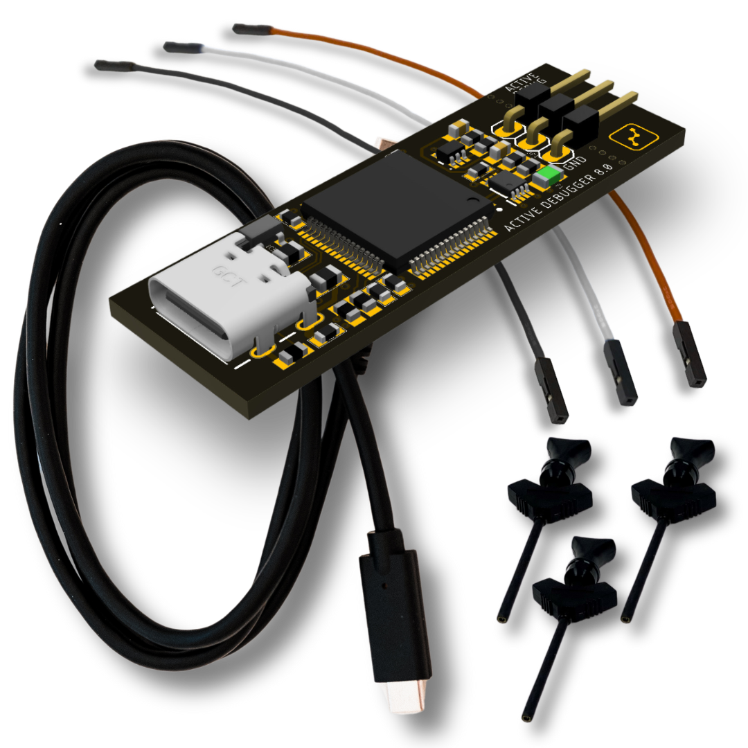
The Active Debugger is a pure firmware instrumentation tool, compact (0.6" × 1.8" × 0.25", 0.2 oz), bus-powered, and focused. It connects via USB and provides two digital channels dedicated exclusively to the Active Debug Port. It monitors one processor or FPGA at a time using a 2-wire (clock + data) interface. It has no analog inputs and no general-purpose logic analyzer channels.
If your goal is firmware visibility, watching variables, states, and debug output alongside your source code without adding a full logic analyzer to your bench, the Active Debugger is the fastest and most affordable way in. It includes 3 color-coded test leads and clips, a USB-C cable, and runs on Windows, Mac, and Linux. It supports the full Active Debug Port library, Live UI widgets, Source Code linkage, Notes, Buffer & Triggers, Custom Decoders on port A, Automation API, and AI Snapshot export.
Active-Pro

The Active-Pro is the full-capability debugger and logic analyzer. It captures 8 digital channels at up to 120 Msps, and 3 analog channels at up to 1 Msps, with hardware bus decoders running at up to 240 Msps. It supports up to four processors or FPGAs simultaneously on the Active Debug Port, and digital channels not assigned to an Active Debug device automatically become general-purpose logic analyzer inputs.
The Active-Pro includes protocol decoding (I²C, SPI, UART, LIN, MDIO, 1-Wire, CHSI, RS-232, DS-101), PacketPresenter for automatic field decoding, Python-scripted Custom Decoders for arbitrary protocols, real-time variable graphing, dynamic current measurement via differential analog input, built-in signal generators, Buffer & Triggers, an Automation API for scripted test control, and data export. Captured data can be exported as an AI Snapshot, a structured text block you paste into any AI assistant to get analysis of your actual firmware behavior in context. It includes 19 color-coded leads and clips, a USB-C cable, and a compact storage case.
Active-Pro Ultra

The Active-Pro Ultra is the super-speed version of the Active-Pro, connected via USB 3.0 SuperSpeed (5 Gbps). It captures 8 digital channels at up to 500 Msps, and 6 analog channels at up to 50 Msps, with digital inputs protected to ±25V. The expanded analog section provides six single-ended channels and two differential pairs (CH1+/CH2- and CH3+/CH4-) with 12-bit resolution.
Everything in the Active-Pro is in the Ultra, with significantly higher digital and analog sample rates, four-processor Active Debug Port support, full bus decoding, PacketPresenter, Custom Decoders, variable graphing, current measurement, signal generators, Automation API, AI Snapshot export, and data export. It includes 21 color-coded leads and clips, a USB 3.0 SuperSpeed cable, and a compact storage case.
Installing the Software
Download the Active-Pro application for Windows, Mac, or Linux from the Downloads page. Run the installer. No manual driver installation is required, the software is the same regardless of which hardware model you have.
The Windows installer also ships with an embedded Python 3 runtime under python_runtime\win64\ next to the executable. This is what powers Custom Decoders by default, there is no separate Python install needed. If you prefer to use your own Python interpreter (for example because your decoder needs a third-party package), you can switch interpreters from Settings → Python Interpreter.
First Launch
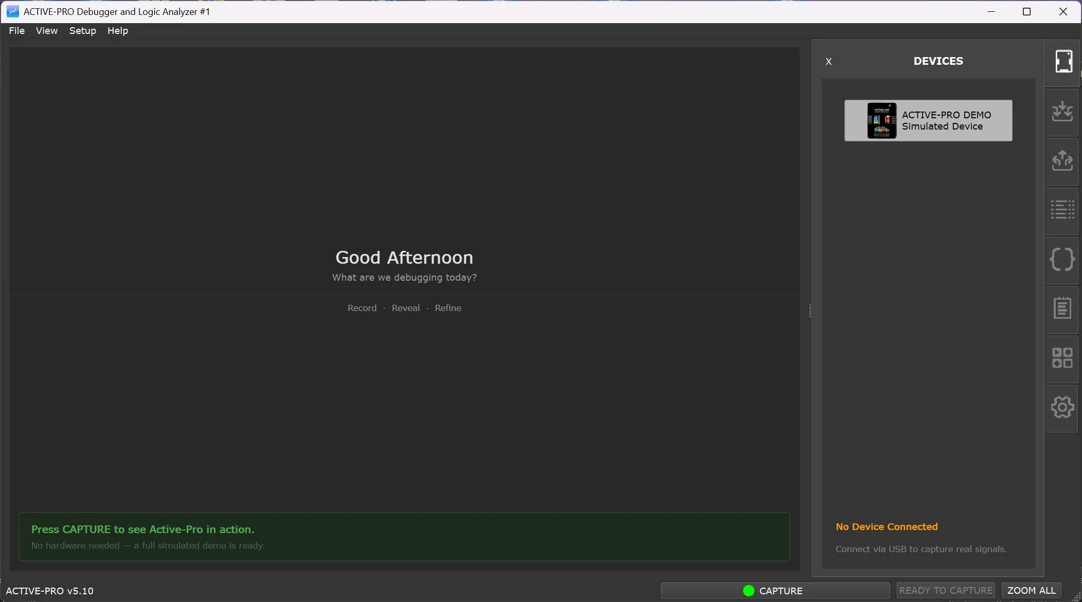
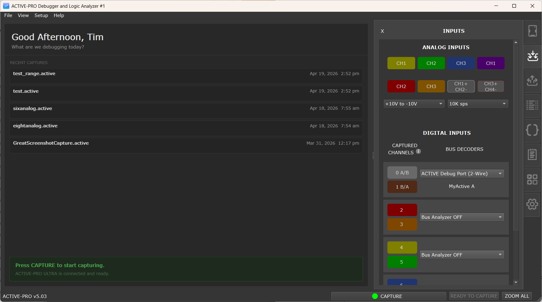
Launch screen without any Active devices connected to the PC
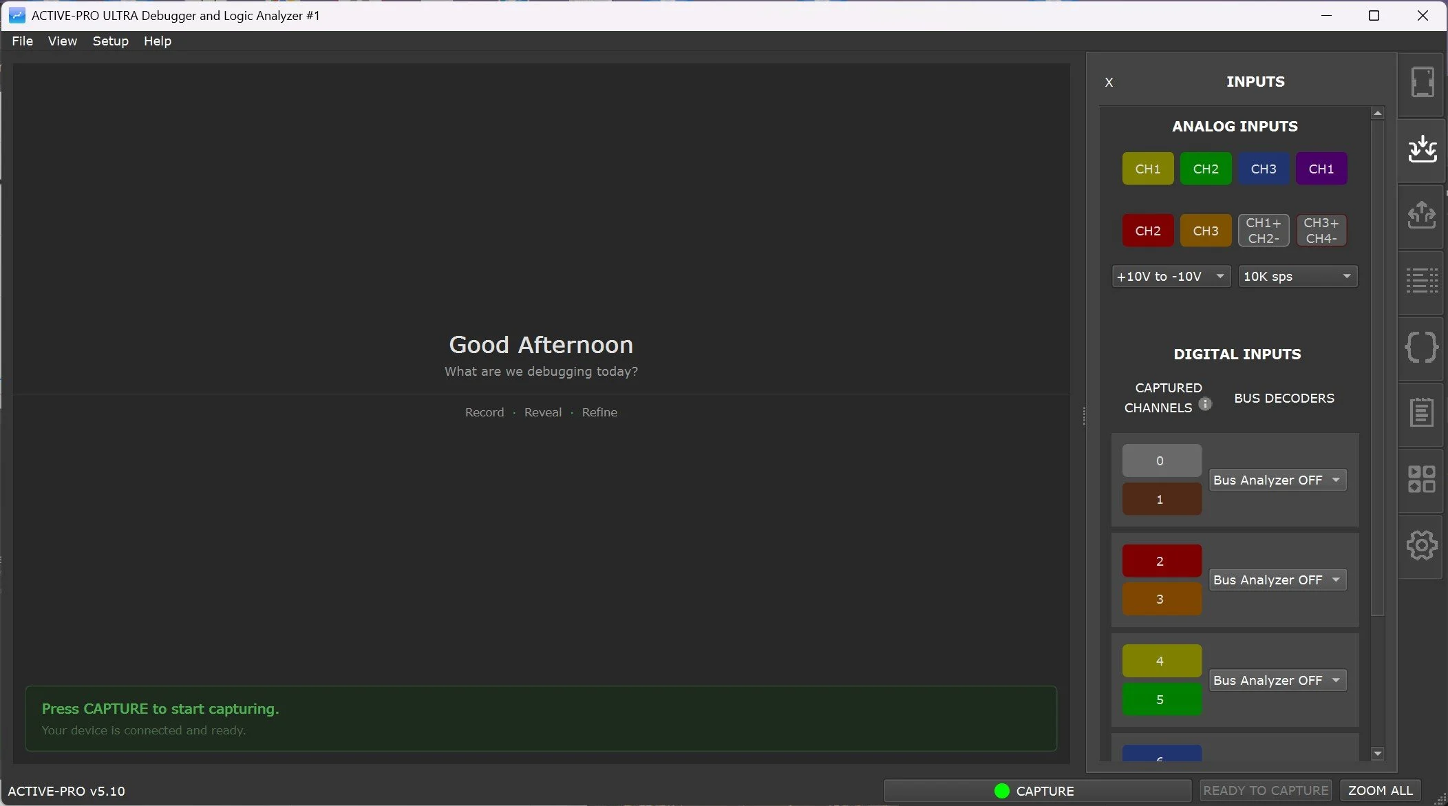
Launch screen with the Active-Pro Ultra device connected to the PC
Launch the application by running ActiveProDebugger. The main window opens immediately and begins scanning for connected hardware. The version string and ready state appear in the status bar at the bottom (Active-Pro v<version> ... READY TO CAPTURE).
If no hardware is connected, the waveform area is empty. The application also runs without hardware, you can open saved .active files and explore the full interface at any time.
Demo Mode: Press Capture without a device connected to launch Demo Mode. It loads a complete simulated capture, including multi-channel bus traffic, analog waveforms, and Active Debug firmware output, so you can explore the full software feature set before your hardware is in hand.
Connecting the Hardware
Plug the included USB-C cable from your Active Firmware Tools device into any available USB port on your computer. The appropriate driver installs automatically.
Active Debugger Connections
The Active Debugger provides two digital pins for the Active Debug Port and one GND. Connect GND to the ground of your target circuit. Connect the two signal leads to the clock and data pins of your Active Debug Port output. The software detects and configures them automatically.
Active-Pro and Active-Pro Ultra Connections

GND - Connect at least one GND to the ground of your target circuit. All GND pins are tied together through resettable polyfuses. Use the GND closest to the signals you're measuring to minimize noise.
Digital Inputs (8 channels) - Used for general-purpose logic capture, hardware bus decoding (I²C, SPI, UART, LIN, MDIO, 1-Wire, CHSI, RS-232, DS-101), and Active Debug Port connections. Channels are arranged in pairs labeled A, B, C, and D, each pair corresponding to one Active Debug device connection. Digital channels not assigned to an Active Debug device are automatically available as general-purpose Logic Analyzer inputs.
Active Debug Port (Devices A, B, C, D) - Each connected processor or FPGA uses 1 wire (UART mode, least-significant bit of the pair) or 2 wires (GPIO/clock+data mode, auto-detected).
Analog Inputs:
- Active-Pro: Three channels. CH1 and CH2 are single-ended (0V to 20V, or ±10V). CH3/CH4 can operate single-ended or as a differential pair for current measurement. Tolerant to ±30V.
- Active-Pro Ultra: Six channels. CH1 through CH6 single-ended (±10V, ±30V tolerant), with two differential pairs: CH1+/CH2- and CH3+/CH4-.
Digital Outputs (D0, D1) - 0V, 3.3V, or tri-state; up to 8mA drive current.
Analog Outputs (A0, A1) - Programmable DC levels (0V to 3.3V) or waveform generation: Sine, Ramp, Triangle, Square.
Test Leads
The included color-coded leads match the channel colors in the software. Push the square connector onto the pin on the pod and attach the mini-grabber clip to the signal on your circuit, IC pins, header posts, test points, or discrete components. If you're designing a new board, a dedicated debug header for GND and your key signals will save time on every future bring-up.
Connecting Leads to Your Target Circuit
Always connect the ground lead first.
- Identify the ground pin on your target circuit. Clip the black (ground) lead to it.
- Connect your signal leads to the appropriate pins.
- For Active Debug Port connections: connect two wires (clock and data) to the pins you designated in your firmware for the Active Debug Port. The exact pins depend on your microprocessor and firmware configuration.
Signal pin assignments for the Active Debug Port depend on your firmware. The Active-Pro software does not dictate which GPIO pins your firmware uses, your firmware calls the ACTIVE library and configures which pins it drives. The hardware simply receives the signal on the corresponding pod input lead.
Choosing a Configuration
Before starting your first capture, configure which decoder mode to use.
Quick Setup
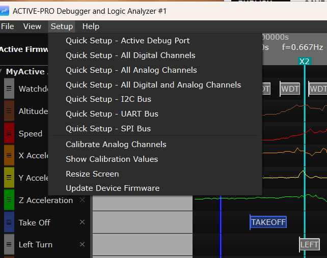
The fastest way to configure a common scenario is through the Setup menu in the menu bar. Each Quick Setup entry applies a complete, correct configuration in one click:
| Quick Setup Entry | What it does | |
|---|---|---|
| Quick Setup - Active Debug Port | Sets Device A to Active Debug Port 2-wire mode | |
| Quick Setup - All Digital Channels | Enables all 8 logic channels | |
| Quick Setup - All Analog Channels | Enables all analog channels | |
| Quick Setup - All Digital and Analog Channels | Enables all logic and analog channels | |
| Quick Setup - I2C Bus | Sets Device A to I2C decode mode | |
| Quick Setup - UART Bus | Sets Device A to UART decode mode | |
| Quick Setup - SPI Bus | Sets Device A to SPI decode mode |
The Setup menu is present on all three hardware models, but on the Active Debugger only the Quick Setup - Active Debug Port entry and the Resize Screen item are useful, the analog/logic Quick Setups and the calibration items target hardware the Active Debugger does not have.
Manual Configuration
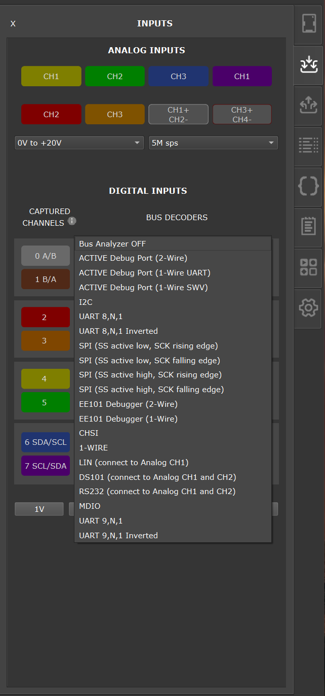
For any model, open the Inputs tab on the right-side panel and select a decoder mode from the BUS DECODERS drop-down for the port you want. (Active-Pro and Active-Pro Ultra show a BUS DECODERS drop-down for each of the four Active Debug Ports; the Active Debugger shows one.) The decoder dropdown groups its entries into three sections:
- Real-Time Hardware Decode - runs on the FPGA inside the pod (Active Debug Port, I²C, UART, SPI, EE101).
- Real-Time Software Decode - runs on the host during capture (1-Wire, LIN, RS-232, MDIO, CHSI, DS101, 9-bit UART).
- Post-Capture Python Decode - opens the Custom Decoder picker to pick a user-supplied Python decoder.
See Decoding for a full list of available decoder modes, and Custom Decoders for the Python decoder system.
On Active-Pro and Active-Pro Ultra, also enable the input channels you want to capture in the Inputs tab. Click the D0-D7 buttons to toggle logic channels on and off.
Making Your First Capture
- Plug in your device - Connect the USB-C cable to your computer. The device appears in the Devices tab automatically.
- Connect Ground - Attach a GND lead to the ground of your target circuit.
- Connect Signals - Attach input leads to the processors, signals, or buses you want to monitor.
- Select Inputs - Choose which channels to capture using Quick Setup (Setup menu) or the Inputs tab. Active Debug Ports and bus signal types are auto-detected.
- (Optional) Configure a trigger - Open the Buffer & Triggers tab and pick a trigger condition if you want the capture to snap to a specific event. See Buffer & Triggers.
- Press Capture - Press Space or click the CAPTURE button. All selected channels begin capturing simultaneously and stream to disk.
- View Waveforms - Use the mouse scroll wheel to zoom, click and drag to pan, or press ZOOM ALL to see everything.
- Stop Capture - Press Space or click STOP CAPTURE when done. Any Custom Decoders attached to ports run automatically after the capture stops.
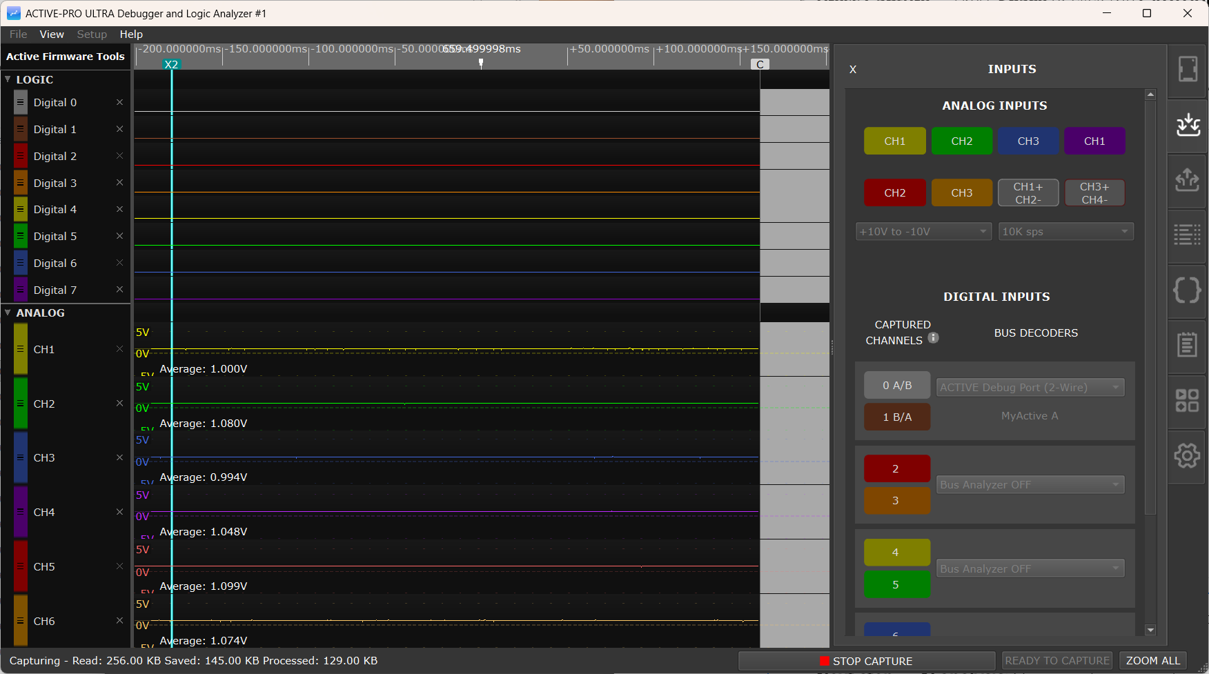
Only signals and channels that have activity are shown on the display automatically, if your firmware only outputs data on one channel, only that channel will appear.
Next step, AI analysis: Once you have a capture, right-click and drag across any region of interest and select Copy AI Snapshot. Paste it into Claude, ChatGPT, or any other AI assistant and ask about what your firmware was doing. See AI Snapshot for details.
Placing Cursors and Making Measurements
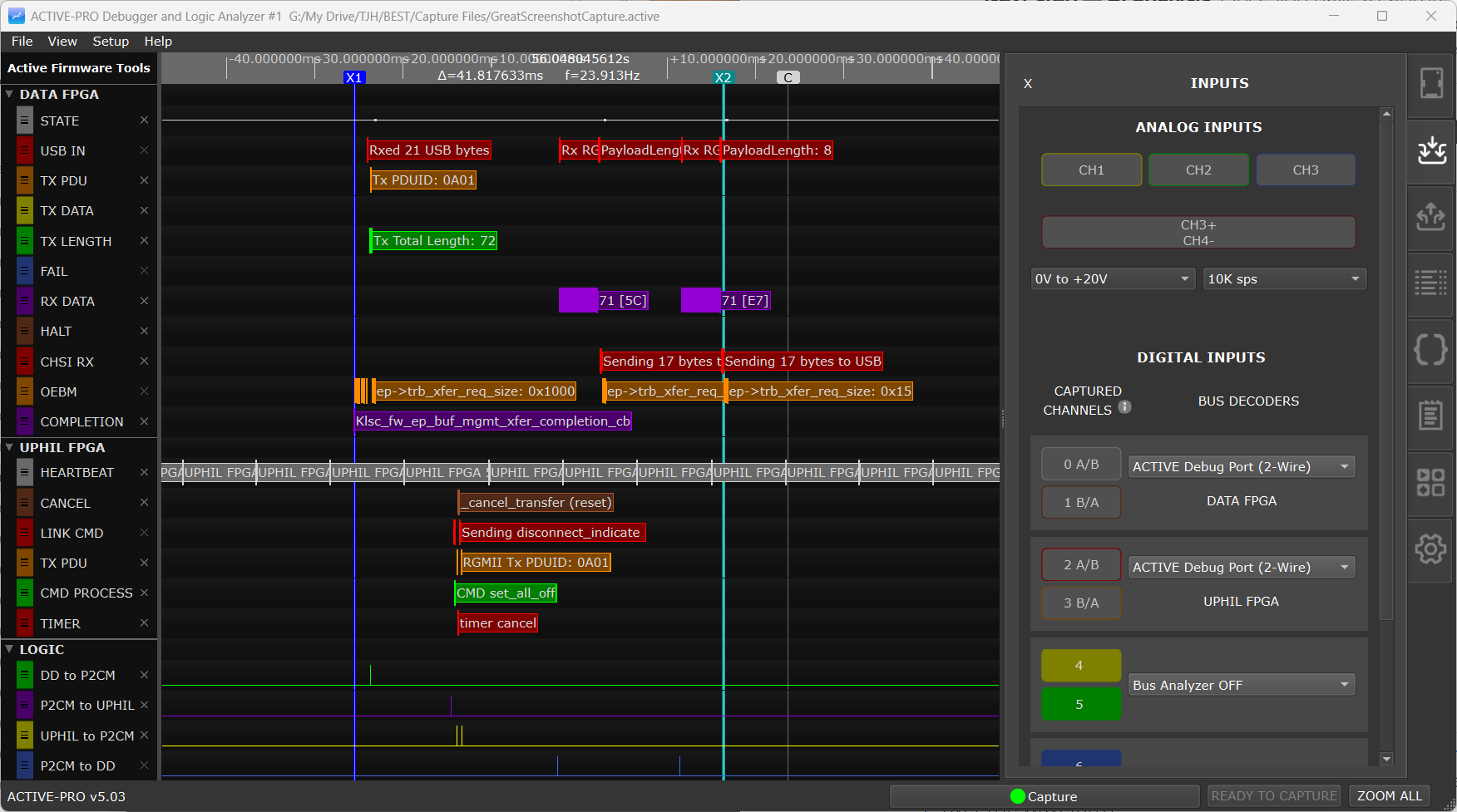
Place X1 cursor: Double-click on the waveform with the left mouse button, or press 1 while hovering over the waveform.
Place X2 cursor: Right double-click on the waveform, or press 2 while hovering.
The timing measurement and delta time between X1 and X2 appear automatically in the status bar. Each analog line also shows the value at the cursor position.
If a trigger has fired in the current capture, the CENTER TRIGGER button in the status bar re-centers the most recent trigger event in the window, and the << / >> buttons step to the previous or next trigger. See Buffer & Triggers.
Opening a Saved Capture
Go to File > Open Capture and select a .active file. Everything is restored exactly as it was when saved: all waveform data, channel names, decoder settings, PacketPresenter definitions, attached Custom Decoder scripts, trigger settings, and notes.
The five most recently opened files are listed under File > Recent Files for quick access.
First-Time Workflow Summary
| Step | What to do | |
|---|---|---|
| 1 | Connect hardware to USB; confirm it appears in the Devices tab | |
| 2 | Configure decoder modes in Inputs tab (or use Setup menu Quick Setup) | |
| 3 | Enable input channels in Inputs tab (Active-Pro/Ultra only) | |
| 4 | (Optional) Configure a trigger in the Buffer & Triggers tab | |
| 5 | Press Space to start capture | |
| 6 | Let your target run; watch data appear | |
| 7 | Press Space to stop capture (Custom Decoders run automatically after stop) | |
| 8 | Scroll wheel to zoom, drag to pan, ZOOM ALL to see everything | |
| 9 | Double-click waveform to place X1 cursor; right double-click for X2 | |
| 10 | Right-click drag to select a range and export or copy data | |
| 11 | File > Save Capture to save your work |