
Active Debug Port - Firmware Integration
The Active Debuggers capture detailed debug information about the execution of firmware, including the graphed values of variables and the exact timings of debug messages as they are executed. The debug information is output from the microprocessors using the firmware routines below using a single line of code to create the Active Debug Port using standard GPIO pins (1 or 2 pins) or a standard SWV port. See the bottom of this page for the active.c and active.h files to include in your firmware projects.
No JTAG interface, no debugger stepping, no halting execution. Your firmware runs at full speed and streams live data to the PC in real time.
There are 2 types of data captured over the Active Debug Port: ACTIVE Text and ACTIVE Value (as well as the standard logic and analog inputs).
ACTIVE Text is character strings and are identical to traditional "printf" output. They are graphed over time as well as listed vertically.
Each debug text output is created by a simple source code line such as:
ACTIVEText( 2, "Button Pressed" );or
ACTIVEprintf( 2, "%d", accum );ACTIVE Value is value data that is then graphed versus time for a visual representation of the data.
Each data point on the waveform is created by a simple source code line such as:
ACTIVEValue ( 3, myvariable );The label on the left of each waveline can also be set from your firmware by calling the ACTIVELabel function.
Overview
You add a small library to your firmware project and call four functions:
| Function | What it does |
|---|---|
ACTIVELabel(channel, name) |
Assigns a human-readable name to a channel number (0–63) |
ACTIVEText(channel, string) |
Sends a text string on the specified channel |
ACTIVEprintf(channel, format, ...) |
Sends a printf-formatted string on the specified channel |
ACTIVEValue(channel, value) |
Sends a numeric value on the specified channel (displayed as a graph) |
Channel numbers are 0 through 63. Each Active Debug Port (A, B, C, D) has its own set of 64 channels.
Active Debug Port Protocol
The Active Debug Port Protocol is sent from an embedded processor to the ACTIVE Debugger Pod to transfer the information from the embedded system to the computer for capture and display.
The data is sent from the embedded processor to the ACTIVE Debugger Pod using the ACTIVE Debug Port, which is available in 3 versions: 1-wire, 2-wire, and SWV (Active-Pro only). Each version of the bus sends the same byte stream.
The 1-Wire ACTIVE Debug Port uses an ASYNC serial UART bus signaling with 8 data bits and no parity at any baud rate that is an exact divide down of 30MHz. Bit alignment is defined by the UART start bit protocol.
The 2-Wire ACTIVE Debug Port uses a SYNC serial bus signaling (CLOCK and DATA lines) with 8 data bits with DATA sampled on the rising edge of the CLOCK rate up to 80M bits per second. This mode can be created easily using an SPI bus using just the SCK and MOSI signals. The bit alignment is determined by the fact that every MSBit is a 0. To sync, the decoder detects if the MSBit is a 1, and if it is, skips a bit until it is never a 1. Once synced, it will remain synced until the 0x7F no longer exists or an MSBit is a 1, at which point a new sync procedure will be completed.
On the Active-Pro, the SWV ACTIVE Debug Port uses the UART encoding mode of SWV (Manchester is not supported) with serial UART bus signaling with 8 data bits and no parity at any baud rate that is an exact divide down of 30MHz. Bit alignment is defined by the UART start bit protocol. SWV outputs 2 bytes for each transmitted character: the first byte is the SWV channel and type indicator, and the second byte is the actual channel data. The Active Debug Port data is contained in these second bytes and the first bytes are ignored.
Supported Platforms
The Active Debug Port library is available for:
- C and C++ (any embedded platform with GPIO or SPI/UART)
- Verilog / SystemVerilog (FPGA)
- VHDL (FPGA)
- Python (MicroPython and similar)
Connection Modes
2-Wire Synchronous Mode (Recommended)
Uses two GPIO pins: one for clock, one for data. This is the highest throughput mode.
If your microcontroller has an SPI peripheral, you can use it for the 2-wire output — configure SPI in transmit-only mode (MOSI + SCK). This offloads the bit-banging to dedicated hardware and maximizes throughput while minimizing firmware overhead.
When to use: When maximum throughput is needed and two GPIO pins are available.
1-Wire UART Mode
Uses one GPIO pin (your MCU's UART TX output). The baud rate must be an exact divisor of 30 MHz (for example: 1 Mbaud, 500 kbaud, 250 kbaud, 115200 baud, etc.). If your MCU has a UART peripheral, it drives this pin automatically.
When to use: When only one GPIO pin is available, or when you want to reuse an existing UART TX pin. Good for MCUs where SPI is not available.
1-Wire SWV (ARM Cortex-M)
Uses the dedicated SWV/ITM debug output pin on ARM Cortex-M processors. No additional GPIO pins required. The microcontroller's built-in ITM hardware sends the data.
When to use: On ARM Cortex-M targets where the SWV pin is accessible and all other GPIO pins are in use.
Sending Text Output
// Label the channels (do this once during initialization)
ACTIVELabel(0, "System");
ACTIVELabel(1, "Motor");
ACTIVELabel(2, "Comms");

// Send text during normal operation
ACTIVEText(0, "Init complete");
ACTIVEText(1, "Motor: starting");

// Send formatted strings like printf
ACTIVEprintf(0, "Temp = %d degrees", temperature);
ACTIVEprintf(2, "RX packet len=%d seq=%d", len, seq);
Each call produces one timestamped text event in the waveform display. The event appears on the channel's waveform row and in the List tab at the exact time it was transmitted.
Tip: Use
ACTIVELabel()at startup to name your channels. If you skip this, channels appear as numbers (Ch0, Ch1, etc.) instead of meaningful names.
Sending Numeric Values
// Send a value that will appear as a graph waveform
ACTIVEValue(3, motor_speed_rpm);
ACTIVEValue(4, temperature_celsius);
ACTIVEValue(5, battery_voltage_mv);
Calls to ACTIVEValue() produce a continuously updated line graph in the waveform display. Each call adds one data point to the graph at the time the call occurred. The result looks like an oscilloscope trace of your variable's value over time — but derived entirely from your firmware, not from hardware probing.
Call ACTIVEValue() regularly (for example, every control loop iteration) to get a smooth graph. Call it only when a value changes if you want a step-function graph.
How Much Data Can the Active Debug Port Handle?
This depends on the connection mode and your MCU's clock:
- 2-wire SPI: Very fast — your SPI peripheral's maximum speed, typically several MHz. At 4 MHz SPI clock, you can send millions of bytes per second, which corresponds to thousands of
ACTIVEprintfcalls per second. - 1-wire UART at 1 Mbaud: Approximately 100,000 bytes per second.
- 1-wire UART at 115200 baud: Approximately 11,500 bytes per second.
Each ACTIVEText or ACTIVEprintf call sends the string length plus a small framing overhead. Short, frequent messages are more efficient than long, infrequent ones.
Practical guidance:
- Do not call ACTIVEprintf inside interrupt service routines unless you are using the SPI peripheral mode and the call is non-blocking.
- Use
ACTIVEValue()instead ofACTIVEprintf()for numeric data that changes every loop — it transmits a 4-byte frame versus a full formatted string. - Disable logic channels you are not using in the Inputs tab to reduce USB bandwidth consumption and leave more headroom for Active Debug Port data.
Active Value Packet Format
The packet format on the Active Bus to send values (as in the ACTIVEValue() routine) is as follows:

Active Text Packet Format
The packet format on the Active Bus to send debug text (as in the ACTIVEText() or ACTIVEprintf() routines) is as follows:

Best Practices
Until we can get an Active Debug Port Hardware Block built inside every microprocessor, use the following Best Practices while using these critical new debug ports on any of your microprocessors:
Debug Output Speed — Since each call to the debug output takes a small amount of time away from the host processor, it is important to use the fastest method of transfer possible. The fastest mode is 2-wire mode, and if you have a built-in SPI hardware block in your MCU even better. The slowest mode is typically the 1-wire mode since it is typically driven by a UART. In this case, use as fast a baud rate as possible.
Volume of Debug Messages — To minimize the impact on your host processor and to minimize the capture file size, try to have debug messages only when needed, and make them as brief as possible while not losing the context of the message.
Turn Off Digital Signals — Although you can capture the digital signals that make up the Active Debug Port, it is not necessary, and if enabled will consume far more data bandwidth than with them off. Turn off the Digital Input channels for your Active Debug Ports (and any other hardware decoded buses as well).
Where is the First Debug Output Message? — There is auto signal detection that automatically determines which signal is clock and which is data. This process takes a whole byte to determine, so it has a 50% chance of misinterpreting the first byte. To solve this, and capture the very first message, either send the message again, or swap the wires to get the very first message. Once the Active-Pro determines the correct signal setup (clock and data detection), it will be correct for future captures.
Using these methods, you can have a powerful debug port into your microprocessor with minimal impact on your application firmware.

ACTIVEValue(25, 89815) using 2-wire mode with a 33MHz SPI hardware block consumes 1.75 µsec

ACTIVEText(24, "Hello") using 2-wire mode with a 33MHz SPI hardware block consumes 2.88 µsec
Using Multiple Active Debug Ports
On the ACTIVE-PRO and ACTIVE-PRO Ultra, four Active Debug Ports (A, B, C, D) can be connected to four separate processors or FPGAs simultaneously, all captured on the same timeline.
Each pod port connects to the appropriate input leads for that port. In the Settings tab, configure each port with the decoder mode matching its connected firmware. The resulting waveform shows all four devices' debug output interleaved on the same time axis.
Common use cases:
- Master and slave MCUs in a multi-processor system
- FPGA logic output alongside ARM firmware output
- Two boards running the same firmware, compared side by side on the same timeline
Instrumentation Strategy
The key to effective Active Debug Port use is strategic instrumentation — not exhaustive instrumentation. Instrument at the points that give you the most information about what is happening.
Good instrumentation targets:
- State machine transitions:
ACTIVEprintf(0, "State: IDLE → ACTIVE")at every state change - Error conditions:
ACTIVEText(1, "ERROR: timeout")immediately when detected - Key variable values at key moments:
ACTIVEprintf(2, "PID: err=%d out=%d", error, output)once per control loop - Interrupt/callback entry and exit for timing analysis: use
ACTIVEValue(3, 1)on entry andACTIVEValue(3, 0)on exit to graph ISR activity over time - Bus transactions: note that hardware bus decoders (I2C, SPI, UART) already capture bus traffic on the same timeline — you do not need to log bus bytes through the Active Debug Port
Avoid:
- Logging every iteration of a tight loop that runs at MHz speeds (generates more data than the port can transmit)
- Logging within time-critical sections where even microseconds of overhead matter (use
ACTIVEValue()which has minimal overhead, or move the logging to after the critical section)
Firmware Routines
The Active-Pro™ captures the debug data from your firmware when you call the following routines.
ACTIVEText(unsigned char channel, unsigned char *string)
This routine outputs the given text on the channel specified.
channel= 0 through 63stringis the null-terminated string to output. These can also be special Control Commands (see below) to control various features of the host capture software.
Example: ACTIVEText(2, "It Happened!"); — Displays "It Happened!" on channel 2 at the current time
ACTIVEprintf(unsigned char channel, unsigned char *printfformatstring, ...)
This routine outputs the printf-like text on the channel specified.
channel= 0 through 63printfformatstringis the null-terminated string to use as in the standard C printf routine...are the parameters used by the format string
Example: ACTIVEprintf(4, "%d: %d", index, data); — Displays "23: 15432" on channel 4 if index = 23 and data = 15432
ACTIVEValue(unsigned char channel, signed long value)
This routine outputs the given value on the channel specified to be graphed over time.
channel= 0 through 63valueis a signed long and can range from –2,147,483,648 to 2,147,483,647
Example: ACTIVEValue(2, ADCValue); — Adds a graphed point at the value 123 on channel 2 at the current time if ADCValue = 123
ACTIVELabel(unsigned char channel, unsigned char *string)
This routine sets the label for the channel specified.
channel= 0 through 63stringis the null-terminated string that becomes the new channel label
Example: ACTIVELabel(2, "State"); — Changes the channel 2 label to "State"
Control Commands
These commands are sent using the string parameter in the call to ACTIVEText().
Play Beep: ACTIVEText(channel, "?cmd=beep")
This command generates an audible BEEP on the computer when it is sent. The channel parameter is ignored.
Example: ACTIVEText(2, "?cmd=beep"); — plays a beep on the computer
Stop Capture: ACTIVEText(channel, "?cmd=stop")
This command stops the capture in progress and displays the trace that has been stored to disk. The channel parameter is ignored.
Example: ACTIVEText(2, "?cmd=stop"); — stops the capture
Restart Capture: ACTIVEText(channel, "?cmd=restart")
This command stops and restarts the capture. This discards the trace that was previously stored to disk. The channel parameter is ignored.
Example: ACTIVEText(2, "?cmd=restart"); — stops and restarts the capture, discarding the previous trace
Zoom All: ACTIVEText(channel, "?cmd=zoomall")
This command zooms the waveform display to show all captured data.
Email Alert: ACTIVEprintf(channel, "?cmd=email&to=addr&msg=text")
Sends an email alert. Requires email configuration in the application.
Embedded Firmware
A key component to the Active-Pro™ system is the firmware that runs on your embedded microcontroller. The microcontroller sends debug information out a pair of general purpose I/O lines (GPIO) whenever you want to see a state, location or variable of your code in real-time operation. To send out this data you call one of the API routines provided below.
The firmware source code below is embedded in your firmware project and provides simple API routines that can be called any time your firmware wants to output information. Similar to printf(...), you can quickly add single lines of code to output a new set of information at exactly the correct time.
To use this firmware source code, copy the source into your project (either inline or in a new source file). Then modify the contents between the MAKE YOUR CHANGES comments. These modifications define how to set the output level of the two GPIO signals as well as other platform-specific settings. See the source code comments below for more details.
Source Code in C
The following is the source code to include in your firmware project. You need to first call ACTIVEInit() at the beginning of your application. You can then place ACTIVEText, ACTIVEValue, or ACTIVEprintf() calls wherever you need to output a debug string or value.
Example usage with BMA400 Accelerometer:
#include <Wire.h>
#include "active.h"
#include "SparkFun_BMA400_Arduino_Library.h"

// Create a new sensor object
BMA400 accelerometer;

// I2C address selection
uint8_t i2cAddress = BMA400_I2C_ADDRESS_DEFAULT; // 0x14

void setup()
{
  ACTIVEInit();  // Call this routine to configure any hardware used by the ACTIVE Bus

  ACTIVEText( 0, "Hello World" );   // Debug Text Output

  // Initialize the I2C library
  Wire.begin();

  // Check if sensor is connected and initialize
  while(accelerometer.beginI2C(i2cAddress) != BMA400_OK)
  {
      // Wait a bit to see if connection is established
      delay(1000);
  }
}

void loop()
{
  // Get measurements from the sensor
  accelerometer.getSensorData();

  // Send the values to the Active-Pro Firmware Debugger
  ACTIVEValue( 1, accelerometer.data.accelX * 100);
  ACTIVEValue( 2, accelerometer.data.accelY * 100);
  ACTIVEValue( 3, accelerometer.data.accelZ * 100);
}
Output of the above code showing the ACTIVEText and ACTIVEValue debug outputs
ACTIVE.C
/* =============================================================
ACTIVE-PRO Firmware Debugger
Debug Output Routines
Provided by activefirmwaretools.com

This file is to be included in your embedded firmware project to
send debug information to the ACTIVE-PRO Firmware Debugger.

If you have any questions or issues, please email us at
support@activefirmwaretools.com.
===============================================================*/

#define ACTIVE_DEBUG_ON // Comment this line out to remove all ACTIVE Debug output from your project

//===============================================================================================
// MAKE MODIFICATIONS FOR YOUR HARDWARE SETUP BELOW THIS LINE
//===============================================================================================
// CHANGE #1:  Add any includes that you need for the interface to your hardware to the ACTIVE bus
#include "project.h"    // for PSoC Projects

// CHANGE #2:  Modify this routine to set up the interface from this processor to the ACTIVE bus
void ACTIVEInit( void )
{
    // Setup your hardware components for the ACTIVE Debug interface.
    // Uncomment the mode you want to use or create your own based on the processor you are using.

    // 1-Wire UART Interface
    // Serial.begin(3000000, SERIAL_8N1, -1, 1);    // Arduino Style: IO1 as output at 3MBaud
    // UART_Start();                                 // PSoC Style

    // 2-wire SPI Interface
    // SPI.begin(18, -1, 19);       // Initialize the SPI block and assign pins
    // SPI.setFrequency(40000000);  // Set the SPI SCK frequency to 40MHz
    SPI_Start();                    // Setup the SPI hardware block (PSoC Style)

    // 2-wire GPIO Interface
    // pinMode(CLOCK_PIN, OUTPUT);   // Set the CLOCK to an Output (Arduino Style)
    // pinMode(DATA_PIN, OUTPUT);    // Set the DATA to an Output (Arduino Style)
    // ACTIVE_CLOCK_GPIO_SetDriveMode( PIN_DM_STRONG );  // PSoC Style
    // ACTIVE_DATA_GPIO_SetDriveMode( PIN_DM_STRONG );   // PSoC Style

    // SWV Interface (UART Mode Only 8,N,1)
    // SWV_Start();    // Setup the SWV hardware (PSoC Style)
}

// CHANGE #3:  Modify this routine to send an array of bytes to the ACTIVE Debug Interface
void SendACTIVEPacket( unsigned char *data, int length )
{
    // Send the packet out the wires. Choose the one type you have selected for this processor.

    // 2-wire SPI Interface
    // SPI.writeBytes( data, length );   // ESP32 Arduino version
    SPI_PutArray( data, length );        // PSoC version

    // 1-wire UART Interface
    // Serial.write( data, length );     // ESP32 Arduino version
    // UART_PutArray( data, length );    // PSoC version

    // 2-wire GPIO Interface
    // unsigned char value;
    // while(length--)
    // {
    //      value = *data++;
    //      if (value & 0x80) ACTIVE_DATA_GPIO_Write(1); else ACTIVE_DATA_GPIO_Write(0); ACTIVE_CLOCK_GPIO_Write(1); ACTIVE_CLOCK_GPIO_Write(0);
    //      if (value & 0x40) ACTIVE_DATA_GPIO_Write(1); else ACTIVE_DATA_GPIO_Write(0); ACTIVE_CLOCK_GPIO_Write(1); ACTIVE_CLOCK_GPIO_Write(0);
    //      if (value & 0x20) ACTIVE_DATA_GPIO_Write(1); else ACTIVE_DATA_GPIO_Write(0); ACTIVE_CLOCK_GPIO_Write(1); ACTIVE_CLOCK_GPIO_Write(0);
    //      if (value & 0x10) ACTIVE_DATA_GPIO_Write(1); else ACTIVE_DATA_GPIO_Write(0); ACTIVE_CLOCK_GPIO_Write(1); ACTIVE_CLOCK_GPIO_Write(0);
    //      if (value & 0x08) ACTIVE_DATA_GPIO_Write(1); else ACTIVE_DATA_GPIO_Write(0); ACTIVE_CLOCK_GPIO_Write(1); ACTIVE_CLOCK_GPIO_Write(0);
    //      if (value & 0x04) ACTIVE_DATA_GPIO_Write(1); else ACTIVE_DATA_GPIO_Write(0); ACTIVE_CLOCK_GPIO_Write(1); ACTIVE_CLOCK_GPIO_Write(0);
    //      if (value & 0x02) ACTIVE_DATA_GPIO_Write(1); else ACTIVE_DATA_GPIO_Write(0); ACTIVE_CLOCK_GPIO_Write(1); ACTIVE_CLOCK_GPIO_Write(0);
    //      if (value & 0x01) ACTIVE_DATA_GPIO_Write(1); else ACTIVE_DATA_GPIO_Write(0); ACTIVE_CLOCK_GPIO_Write(1); ACTIVE_CLOCK_GPIO_Write(0);
    // }

    // SWV Interface (UART Mode Only 8,N,1)
    // while(length--) ITM_SendChar( *data++ );   // PSoC version
}
//===============================================================================================
// MAKE MODIFICATIONS FOR YOUR HARDWARE SETUP ABOVE THIS LINE ONLY
//===============================================================================================

#ifdef ACTIVE_DEBUG_ON

#define MAX_ACTIVE_LENGTH 255
unsigned char ACTIVETxBuffer[MAX_ACTIVE_LENGTH];

void ACTIVEValue( int channel, int value )
{
    int length = 0;
    char done = 0;
    char positive = (value >= 0);

    ACTIVETxBuffer[length++] = 0x7F;            // Every ACTIVE packet starts with 0x7F
    ACTIVETxBuffer[length++] = channel & 0x3F;  // Bit7=0, Bit6=0 = Value; Bits5:0 = channel

    while(!done)
    {
        if ((positive && (value >= 32)) || (!positive && (value < -32)))
        {
            ACTIVETxBuffer[length++] = value & 0x3F;
            value = value >> 6;
        }
        else
        {
            ACTIVETxBuffer[length++] = (value & 0x3F) | 0x40;
            done = 1;
        }
    }

    SendACTIVEPacket(ACTIVETxBuffer, length);
}

void ACTIVEText( int channel, char *string )
{
    int length = 0;

    ACTIVETxBuffer[length++] = 0x7F;
    ACTIVETxBuffer[length++] = 0x40 | (channel & 0x3F);  // Bit7=0, Bit6=1 = Text; Bits5:0 = channel

    while(*string)
    {
        if (length >= MAX_ACTIVE_LENGTH-1)
            break;
        ACTIVETxBuffer[length++] = *string & 0x7F;
        string++;
    }
    ACTIVETxBuffer[length++] = 0;  // String termination

    SendACTIVEPacket(ACTIVETxBuffer, length);
}

#include "stdio.h"
#include <stdarg.h>
char ACTIVEstr[MAX_ACTIVE_LENGTH];
void ACTIVEprintf( int channel, char *format, ... )
{
    va_list arglist;
    va_start( arglist, format );
    vsprintf( ACTIVEstr, format, arglist );
    va_end( arglist );
    ACTIVEText( channel, ACTIVEstr );
};

#else
void ACTIVEInit( void ) {};
void ACTIVEText( int channel, char *string ) {};
void ACTIVEValue( int channel, int value ) {};
void ACTIVEprintf( int channel, char *format, ... ) {};
#endif
ACTIVE.H
#ifndef ACTIVE_DEBUG_H
#define ACTIVE_DEBUG_H

void ACTIVEInit( void );                              // Initialize any hardware needed by the ACTIVE Interface
void ACTIVEValue( int channel, int value );           // Output a Value for this channel
void ACTIVEText( int channel, char *string );         // Output Text for this channel
void ACTIVEprintf( int channel, char *format, ... );  // printf-like function with variable argument list

// Define helpful macros for sending debug command messages
#define ACTIVELabel(channel,string)  ACTIVEText( (channel) , "?cmd=label&label=" string )
#define ACTIVEBeep()    ACTIVEText( 0 , "?cmd=beep" )
#define ACTIVEStop()    ACTIVEText( 0 , "?cmd=stop" )
#define ACTIVERestart() ACTIVEText( 0 , "?cmd=restart" )

#endif
Source Code in Verilog
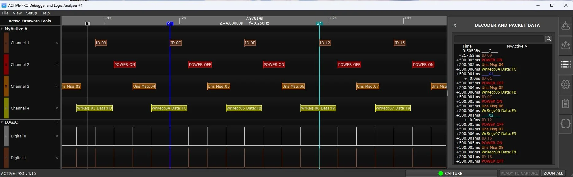
Below is an example Verilog (SystemVerilog) example that sends 4 example debug messages from your Verilog RTL. The output of this code on the Active-Pro looks like this:
//===================================================================================
// Example Top module - replace with your code.
// This shows how to instantiate the ACTIVEPRO module and use it in your RTL.
//===================================================================================
module top (
    input  clock,
    input  reset_n,
    output active_clock,
    output active_data
);

    reg [511:0] active_message;
    reg [5:0]   active_channel;
    reg         active_wr;

    ACTIVEPRO myactivepro (
        .reset_n      (reset_n),
        .clock        (clock),
        .active_data  (active_data),
        .active_clock (active_clock),
        .message      (active_message),
        .channel      (active_channel),
        .wr           (active_wr)
    );

    // ... stimulus and message generation logic ...
    // See full source at activefirmwaretools.com

endmodule

//===================================================================================
// Active-Pro Debug Output Module
//===================================================================================
module ACTIVEPRO (
    input         reset_n,
    input         clock,
    output        active_data,
    output        active_clock,
    input  [511:0] message,
    input  [5:0]   channel,
    input          wr
);
    // Serializes message to the Active Debug Port 2-wire output.
    // Output clock is half the input clock frequency.
    // See full source at activefirmwaretools.com
endmodule
The full Verilog source including the hex-to-ASCII lookup table, ACTIVEPRO module, byte serial shifter, and complete example top module is available at activefirmwaretools.com.
Source Code in VHDL
A complete VHDL conversion of the Verilog implementation is available, including:
activepro_utilspackage withascii_vec,zext512,nibble_to_ascii, andbyte_to_hex_asciihelper functionsbyte_serial_shifterentityACTIVEPROentity with identical port interface to the Verilog version- Example
topentity showing all four message types
The VHDL source is available at activefirmwaretools.com.
Source Code in Python
# =============================================================
# ACTIVE-PRO Firmware Debugger - Debug Output Routines
# Provided by activefirmwaretools.com
# =============================================================

ACTIVE_DEBUG_ON = True

if ACTIVE_DEBUG_ON:
    import spidev
    import serial

    def ACTIVEInit():
        global spi, uart
        # 2-wire SPI Interface
        spi = spidev.SpiDev()
        spi.open(0, 0)  # Adjust bus and device as per your setup
        spi.max_speed_hz = 40000000
        # 1-wire UART Interface
        uart = serial.Serial()
        uart.baudrate = 3000000
        uart.port = '/dev/ttyS0'  # Adjust as per your setup
        uart.open()

    def SendACTIVEPacket(data):
        spi.xfer2(data)        # 2-wire SPI Interface
        # uart.write(bytearray(data))  # 1-wire UART Interface

    MAX_ACTIVE_LENGTH = 255
    ACTIVETxBuffer = bytearray(MAX_ACTIVE_LENGTH)

    def ACTIVEValue(channel, value):
        length = 0
        done = False
        positive = value >= 0
        ACTIVETxBuffer[length] = 0x7F; length += 1
        ACTIVETxBuffer[length] = channel & 0x3F; length += 1
        while not done:
            if (positive and value >= 32) or (not positive and value < -32):
                ACTIVETxBuffer[length] = value & 0x3F; value >>= 6; length += 1
            else:
                ACTIVETxBuffer[length] = (value & 0x3F) | 0x40; done = True; length += 1
        SendACTIVEPacket(ACTIVETxBuffer[:length])

    def ACTIVEText(channel, string):
        length = 0
        ACTIVETxBuffer[length] = 0x7F; length += 1
        ACTIVETxBuffer[length] = 0x40 | (channel & 0x3F); length += 1
        for char in string:
            if length >= MAX_ACTIVE_LENGTH - 1: break
            ACTIVETxBuffer[length] = ord(char) & 0x7F; length += 1
        ACTIVETxBuffer[length] = 0; length += 1
        SendACTIVEPacket(ACTIVETxBuffer[:length])

    def ACTIVEprintf(channel, format_string, *args):
        ACTIVEText(channel, format_string % args)

else:
    def ACTIVEInit(): pass
    def ACTIVEText(channel, string): pass
    def ACTIVEValue(channel, value): pass
    def ACTIVEprintf(channel, format_string, *args): pass