
Signal Generators
Available on: ACTIVE-PRO · ACTIVE-PRO Ultra
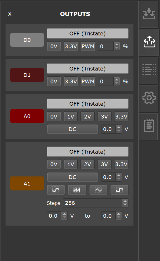
The ACTIVE-Pro has built-in digital and analog signal generators. These are controlled from the Outputs tab on the right-side panel, and can also be fully automated via the Automation API.
Digital Signal Generators (D0 and D1)
The ACTIVE-Pro has 2 Digital Signal Generators built in. It outputs a digital voltage on the D0 and D1 signals.
Each of the digital lines can have one of the modes below by selecting the associated radio button:
| Mode | Description |
|---|---|
| Tristate | Pin is not driven — high impedance. Safe default. |
| Logic Low (0V) | Pin is driven to 0V |
| Logic High (3.3V) | Pin is driven to 3.3V |
| PWM | Pulse Width Modulator — square wave output at 250 kHz (ACTIVE-PRO) or 390 kHz (ACTIVE-PRO Ultra). A duty cycle control sets the on-time percentage from 0% to 100%. |
Output drive capability: 8 mA max per pin.
Analog Signal Generator (A0 and A1)
The ACTIVE-Pro has an Analog Signal Generator built in. It outputs a voltage pattern on the A0 and A1 signals.
A0 can be set to:
| Mode | Description |
|---|---|
| Tristate | Not driven (high impedance) |
| 0 V | Fixed DC output at 0 V |
| 1 V | Fixed DC at 1 V |
| 2 V | Fixed DC at 2 V |
| 3 V | Fixed DC at 3 V |
| 3.3 V | Fixed DC at 3.3 V |
| DC | Custom DC voltage, set with the voltage spin box |
A1 supports all of the above A0 modes, plus waveform output modes:
| Mode | Description |
|---|---|
| Sine | Sinusoidal waveform |
| Ramp | Linear ramp waveform, sweeping from minimum to maximum voltage |
| Square | Square wave (50% duty cycle) |
| Triangle | Triangular waveform |
For waveform modes, set the minimum and maximum output voltage using the controls (0V to 3.3V range). Frequency is adjusted via the Steps setting — the number of steps per waveform cycle. Each step is 4 µsec.
Waveform frequency range:
- ACTIVE-PRO: 62.5 Hz to 25 kHz
- ACTIVE-PRO Ultra: 62.5 Hz to 7.25 kHz
Tips
Testing power supply response: Set A0 to a DC level matching your circuit's supply voltage, then switch it to 0 V and watch the analog input channels on the same timeline to measure your power supply's response time.
ADC transfer function: Drive A1 with a ramp waveform and connect it to your target's ADC input while monitoring the ADC readings via the Active Debug Port. This gives you a complete ADC transfer function with one capture.
All output settings can also be controlled via the Automation API.